Liquid cooling energy converting equipment
A technology of energy conversion equipment and liquid cooling, applied in the field of liquid cooling energy conversion equipment and flow paths
- Summary
- Abstract
- Description
- Claims
- Application Information
AI Technical Summary
Problems solved by technology
Method used
Image

Examples
no. 1 example
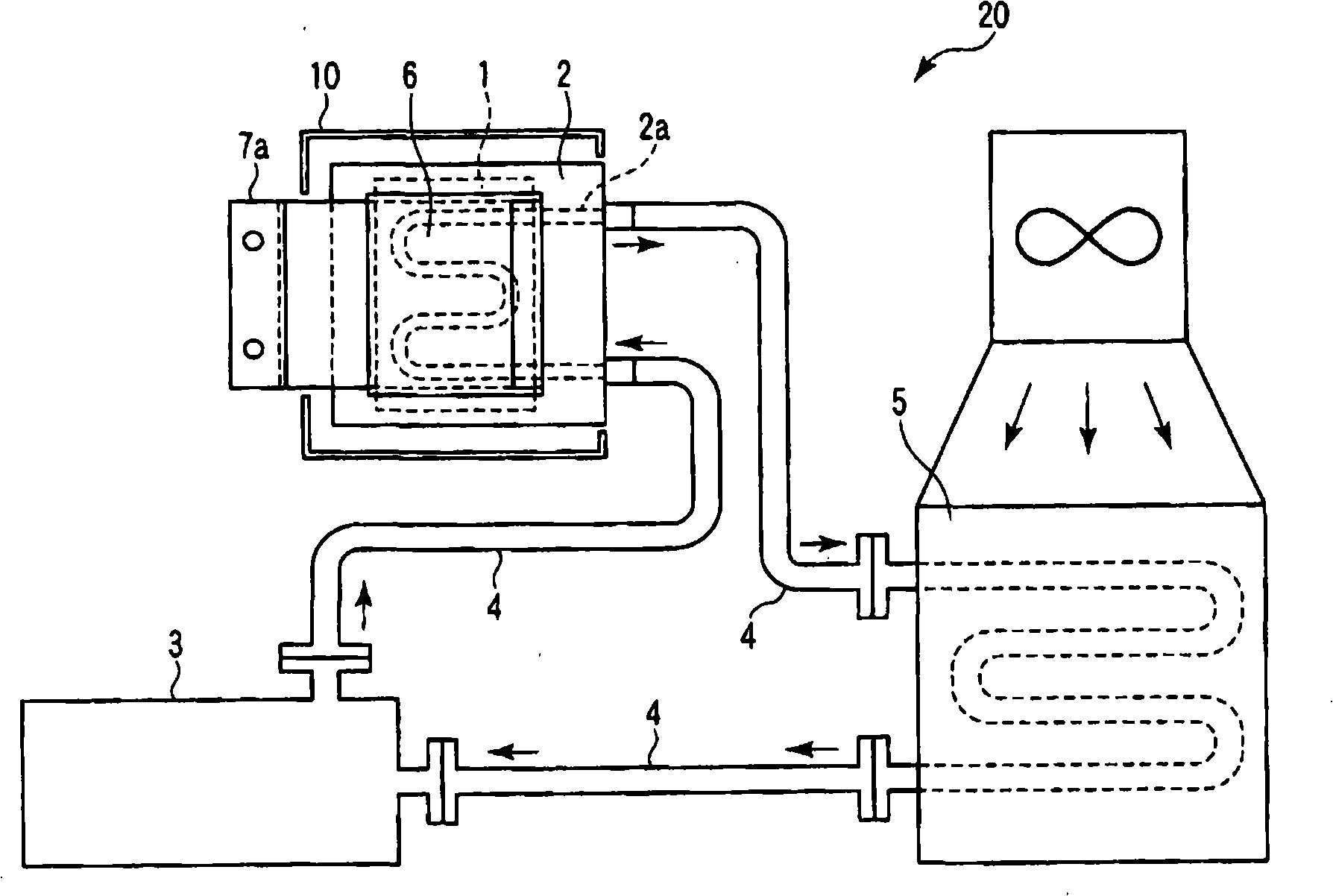
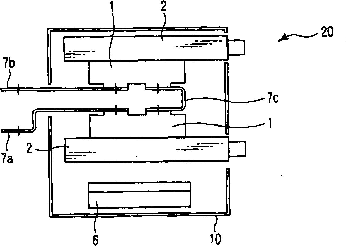
[0028] Attached figure 1 It is a side view showing the entire configuration of the liquid-cooled energy conversion device 20 of the first embodiment of the present invention. Attached figure 2 It is a top view showing the configuration of the peripheral portion of the semiconductor element 1 of the device 20 of the present embodiment. Attached figure 1 with 2 In, with attached Figure 13 with 14 Identical components in the diagram are denoted by the same reference numerals, a detailed description thereof is omitted, and different components will be mainly described. In the following embodiments, repeated description will be similarly omitted.
[0029] The device 20 includes two semiconductor elements 1, two liquid cooling fins 2, a strobe amplifier substrate 6, a main circuit conductor 7a, 7b, 7c, a pump 3, and three tubes 4, a heat exchanger 5, and a frame unit 10.
[0030] A unit is formed by two semiconductor elements 1, two liquid cooling fins 2, a gate amplifier substrate ...
no. 2 example
[0043] Attached Figure 4 It is a top view in which the configuration of the peripheral portion of the semiconductor 1 of the liquid-cooled energy conversion device 20B according to the second embodiment of the present invention is viewed from above.
[0044] The device 20B is constructed so that the insulating plate 8 is sandwiched in the attached figure 2 The device 20 of the first embodiment is shown in between the main circuit conductors 7a and 7b. The configuration of the other parts is the same as in the first embodiment.
[0045] The electric potentials of the main circuit conductor 7a and the main circuit conductor 7b are different. The potentials of the terminals of the two semiconductor elements 1 are also different. The insulating plate 8 electrically insulates between the main circuit conductor 7a and the main circuit conductor 7b. The insulating plate 8 electrically insulates between the electrical terminals of the two semiconductor elements 1 facing each other.
[0...
no. 3 example
[0050] Attached Figure 6 A top view is shown in which the configuration of the peripheral portion of the semiconductor element 1 of the liquid-cooled energy conversion device 20D according to the third embodiment of the present invention is viewed from above.
[0051] The device 20D is configured to connect the strobe amplifier substrate 6 and the attached Figure 4 The liquid cooling fins 2 in 20B shown in FIG. 2 are arranged at right angles. Except for this point, the third embodiment has the same configuration as the second embodiment.
[0052] The liquid cooling fin 2 is provided at a position where a part of the flow path 2a connected to the tube 4 is placed on the front (front side) of the unit when the device 20D is installed on the locomotive.
[0053] Since the gate amplifier substrate 6 and the liquid cooling fin 2 are arranged at right angles, the gate amplifier substrate 6 is arranged in a direction perpendicular to the direction of the main circuit current flowing in...
PUM
 Abstract
Description
Claims
Application Information
 - R&D
- Intellectual Property
- Life Sciences
- Materials
- Tech Scout
- Unparalleled Data Quality
- Higher Quality Content
- 60% Fewer Hallucinations
Browse by: Latest US Patents, China's latest patents, Technical Efficacy Thesaurus, Application Domain, Technology Topic, Popular Technical Reports.
© 2025 PatSnap. All rights reserved.Legal|Privacy policy|Modern Slavery Act Transparency Statement|Sitemap|About US| Contact US: help@patsnap.com