Automatic gain control apparatus and method in wireless telecommunication system

An automatic gain control and gain control technology, which is applied in the direction of gain control, amplification control, transmission system, etc., can solve problems such as changes in input signal strength

Inactive Publication Date: 2009-01-14
POS DATA CO LTD
View PDF0 Cites 5 Cited by
  • Summary
  • Abstract
  • Description
  • Claims
  • Application Information

AI Technical Summary

Problems solved by technology

In particular, when synchronization is not achieved at the start of PSS operation, variations in input signal strength can cause serious problems

Method used


Image

  • Automatic gain control apparatus and method in wireless telecommunication system
  • Automatic gain control apparatus and method in wireless telecommunication system
  • Automatic gain control apparatus and method in wireless telecommunication system

Examples


Embodiment Construction

[0024] Hereinafter, exemplary embodiments of the present invention will be described in detail with reference to the accompanying drawings. Well-known functions and constructions are not described in detail since they would obscure the invention in unnecessary detail.

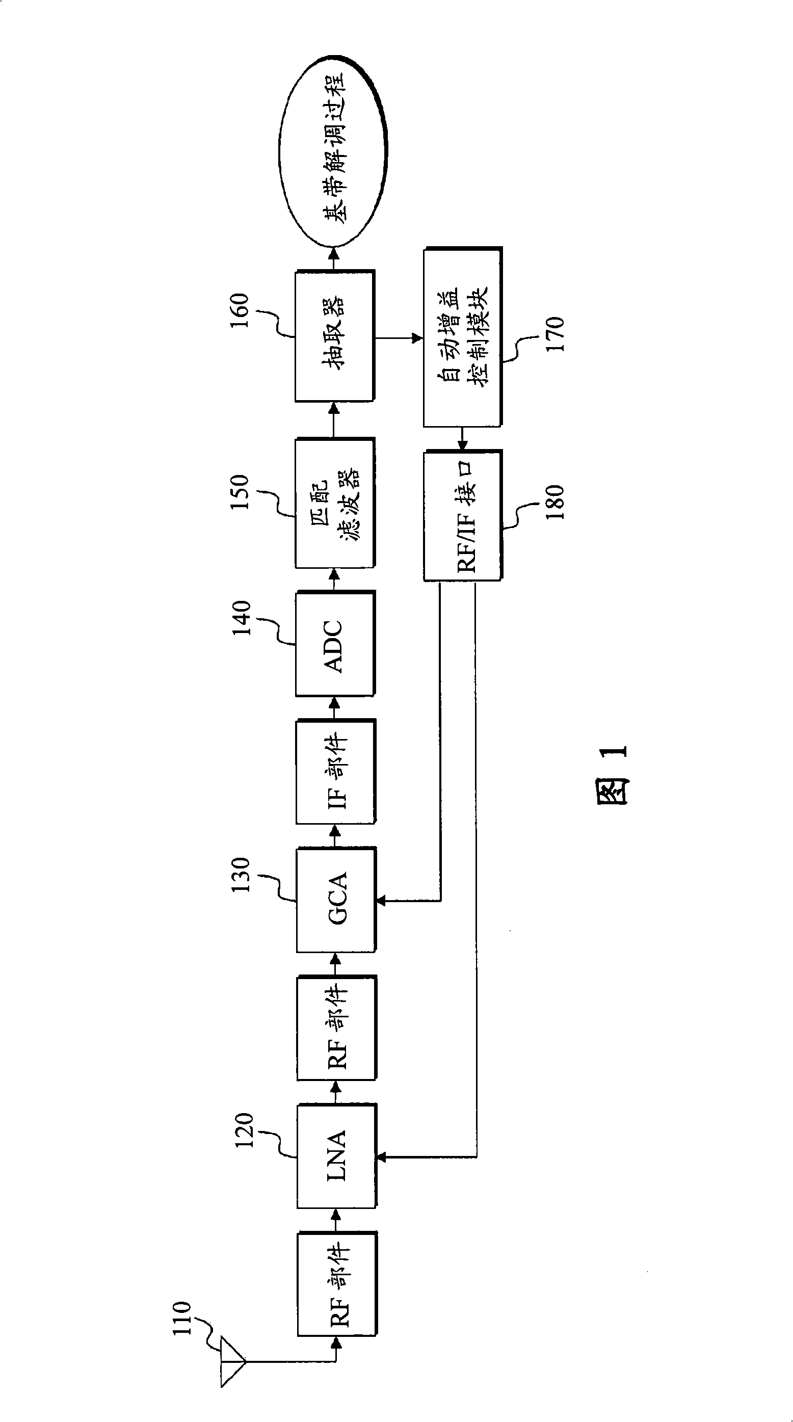
[0025] The configuration of an automatic gain control device of a wireless telecommunication system associated with the present invention is schematically described below with reference to FIG. 1 .

[0026] A signal received from the antenna 110 passes through RF components and is transmitted to a low noise amplifier (LNA) 120 . LNA 120 is an amplifier for minimizing noise generated in a Portable Subscriber Station (PSS), and it is the first amplifier placed on the receive path.

[0027] A signal amplified by the LNA 120 passes through an RF part and is then input to a gain control amplifier (GCA) 130 which is an amplifier that performs a gain control function by amplifying an input signal. Meanwhile, the sig...


PUM


Abstract

The present invention relates to an automatic gain control apparatus and method in a wireless telecommunication system which measures the strength of received signals using preamble symbols and automatically control the gain of an amplifier based on the measurement results. The automatic gain control apparatus and method according to present invention performs automatic gain control of measuring sample power in a sample unit for input signals, acquiring a sample power average value during a unit symbol period, detecting a maximum value during one frame period for the acquired sample power average value and then calculating a gain control value based on it.

Description

technical field [0001] The present invention relates generally to automatic gain control apparatus and methods in wireless telecommunication systems, and more particularly to automatic gain control apparatus and methods in wireless telecommunication systems that utilize preamble symbols to measure the strength of received signals and based on The measurement results automatically control the gain of the amplifier, which can be applied in portable Internet systems. Background technique [0002] Typically, in a wireless telecommunication system, due to distance changes between a radio access station (RAS) and a portable subscriber station (PSS), interference caused by obstacles, movement of the PSS, and changes in the PSS environment, there is an incoming signal The characteristic that the intensity cannot be maintained uniformly and changes within a certain range. In this case, in order to maintain a uniform signal strength transmitted to the baseband demodulator of the PSS,...

Claims


Application Information

Patent Timeline
Patent Type & Authority Applications(China)
IPC IPC(8): H04L25/12
CPCH04L27/2647H03G3/3078H03G3/3068H04L25/12
Inventor 吴知明
Owner POS DATA CO LTD
Why Eureka
Try Eureka