Printer roller

A technology for printing machines and adjusting rollers, applied in printing machines, printing, rotary printing machines, etc., can solve problems such as insufficient help, and achieve the effect of eliminating gear loads

Inactive Publication Date: 2009-01-21
HEIDELBERGER DRUCKMASCHINEN AG
View PDF3 Cites 2 Cited by
  • Summary
  • Abstract
  • Description
  • Claims
  • Application Information

AI Technical Summary

Problems solved by technology

[0008] The pressure rollers and cylinders described in the latter two documents are not really helpful enough to solve the problems existing in dampening mechanisms equipped with anilox devices

Method used


Image

  • Printer roller
  • Printer roller
  • Printer roller

Examples


Embodiment Construction

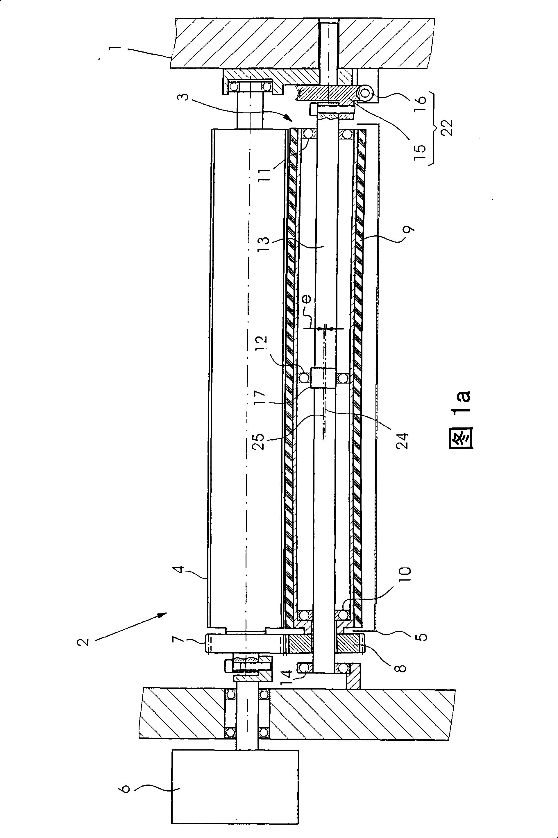
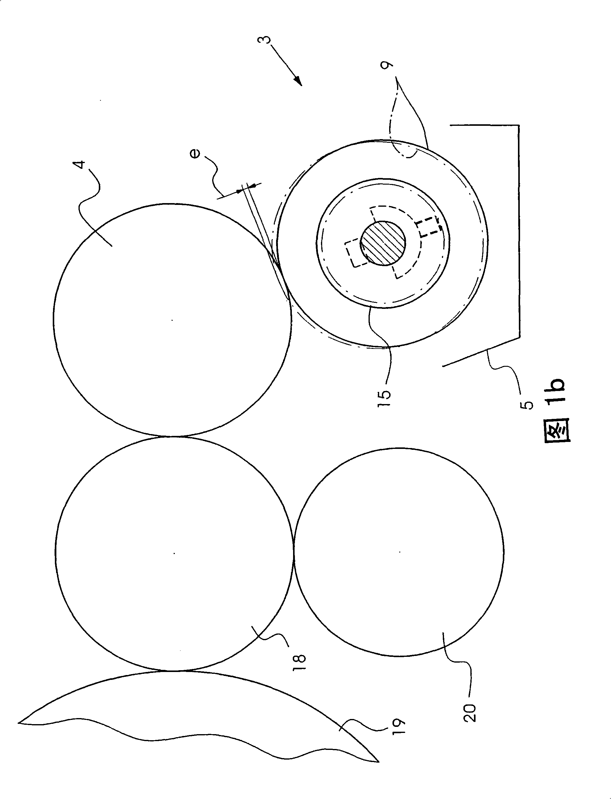
[0039] FIGS. 1 a , 2 a and 3 a show a printing press 1 for offset lithography comprising a dampening unit 2 with a roller 3 and a further roller 4 . The roll 3 is a flooded roll and is arranged in a dampening tank 5 for drawing dampening agent from the dampening tank. The roller 3 rests against the further roller 4 in order to transfer the picked up dampening agent to the further roller. An electric motor 6 drives the other roller 4 in rotation. A first gear 7 , which is rotationally fixed to the further roller 4 , meshes with a second gear 8 . The second gear wheel 8 is non-rotatably connected to the tubular or hollow-cylindrical roller jacket 9 of the roller 3 . The roll jacket 9 is rotatably supported on a fixed shaft 13 via roll-end-side or axially outer pivot bearings 10 , 11 and a pivot bearing 12 situated between or in between the aforementioned pivot bearings. The outer diameter of these pivot bearings 10, 11, 12 is substantially equal to the inner diameter of the r...


PUM


Abstract

The invention relates to a printer roller (3), which comprises a fixed axis (13) and a roller jacket (9) borne on the fixing axis (13) through a first pivot bearing (10), a second pivot bearing (11) and a third pivot bearing (12). The third pivot bearing (12) is not aligned with the first pivot bearing (10) and the second pivot bearing (11), and disposed between the first and second pivot bearing; the roller jacket (9) is connected with a first gear (8) without relative rotation; and the gear and the roller jacket (9) rotates around the fixed axis (13) together.

Description

technical field [0001] The invention relates to a printing press roll, a dampening unit equipped with the printing press roll and a method for adjusting the roll. Background technique [0002] The invention stems from the following background: in offset printing presses with dampening mechanism, when printing particularly small-format printed sheets, in the side areas lying outside the format width, undesired friction between printing ink and dampening agent occurs. Alternative action, due to the overdosing of printing ink or dampening agent and a perceptible reduction in the print quality. If the printing press has a conventional inking unit with inking zones, the above-mentioned alternation can be counteracted by adjusting the inking zones. By correspondingly adjusting the ink regions lying outside the format width, the ratio between printing ink and dampening agent can be influenced in such a way that interference effects are suppressed. However, this possibility does n...

Claims


Application Information

Patent Timeline
Patent Type & Authority Applications(China)
IPC IPC(8): B41F7/24B41F7/40
CPCB41F13/28F16C13/024B41F13/26B41F7/26B41F31/305B41F31/26
Inventor D·布赫莱特J·米歇尔斯D·沙夫拉特W·舍恩伯格B·施瓦布M·蒂勒曼M·德萨姆
Owner HEIDELBERGER DRUCKMASCHINEN AG
Why Eureka
Try Eureka