
Biplane x-ray system

An X-ray, double-sided technology, applied in the field of X-ray double-sided equipment, can solve the problem of unable to shoot to meet the integrity conditions and other problems

Inactive Publication Date: 2009-01-21
SIEMENS AG
View PDF0 Cites 9 Cited by
  • Summary
  • Abstract
  • Description
  • Claims
  • Application Information

AI Technical Summary

Problems solved by technology

It is not possible to photograph such a scanned track that satisfies the so-called integrity conditions

Method used


Image

  • Biplane x-ray system
  • Biplane x-ray system
  • Biplane x-ray system

Examples


Embodiment Construction

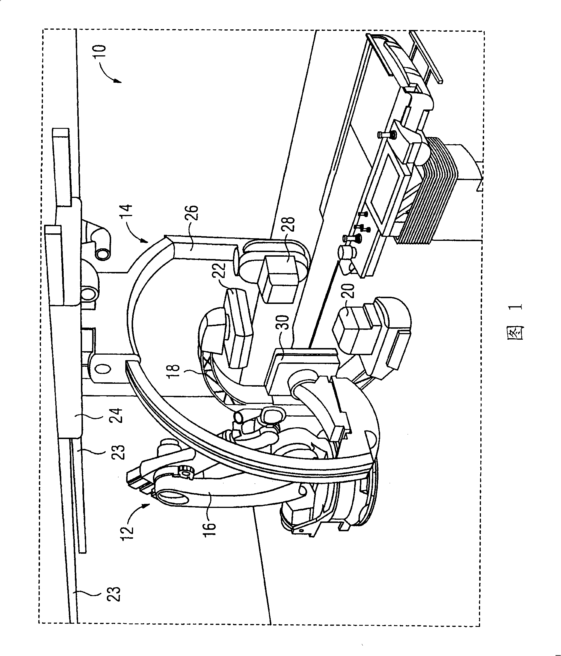
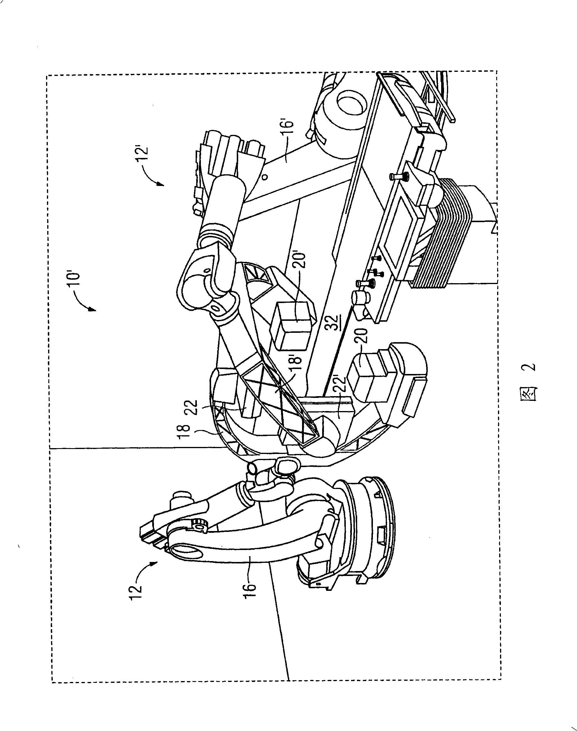
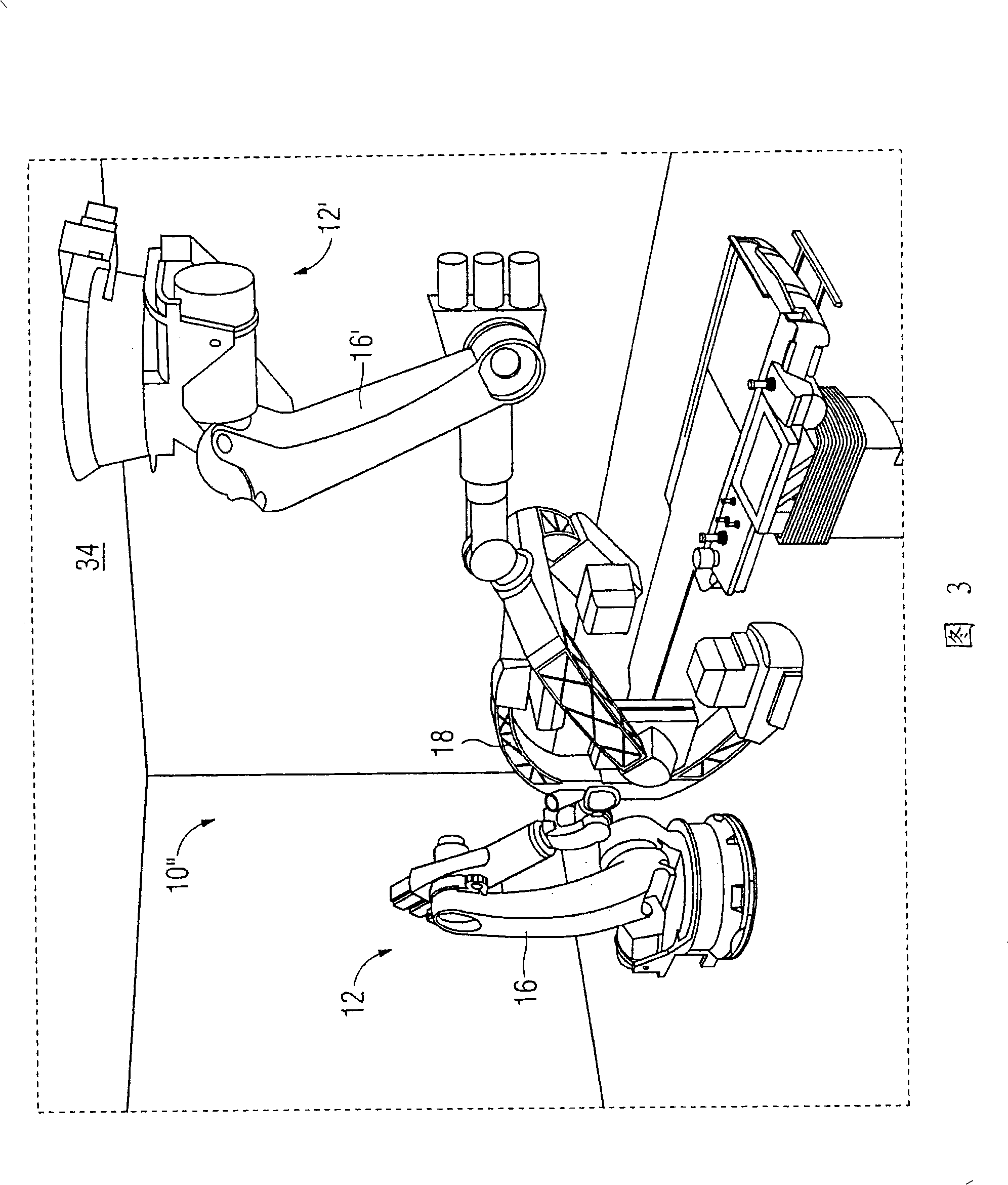
[0023] The X-ray double-sided device shown in FIG. 1 , designated as a whole by the reference numeral 10 , comprises a first X-ray imaging device 12 and a second X-ray imaging device 14 . The first X-ray imaging device 12 includes a six-axis crank arm robot 16 on which a C-arm 18 carrying an X-ray radiation source 20 and an X-ray detector 22 is fixed. The second X-ray imaging device 14 comprising a support movable on a guide rail 13 has a movable X-ray C-arm, on which an X-ray radiation source 28 and an X-ray detector 30 are likewise fixed . The difference between the X-ray double-sided equipment 10 and the traditional X-ray double-sided equipment is that a robot 16 is used. The robot 16 has significantly greater degrees of freedom than conventional X-ray C-arm systems. Can reach the specific position of X-ray radiation source 20 and X-ray detector 22 and X-ray radiation source 28 and X-ray detector 30 thus, that is to say, this X-ray double-sided equipment 10 and traditiona...


PUM


Abstract

The invention discloses an X ray double surface equipment, in which, a robot (16) is adopted for moving at least one pair of X ray radioactive source (20) and X ray detector (22). The robot can be a crank arm robot (16) with a X ray C shaped arm. The X ray radioactive source (40) and the X ray detector (42) can be suspended on the roof (34) of the room by the robot arms (36, 38).

Description

technical field [0001] The invention relates to an X-ray double-sided device. It is known that such an X-ray double-sided device includes two X-ray imaging devices, each of which includes an X-ray radiation source, an X-ray detector and a device for moving the X-ray radiation source and the X-ray detector. device. Background technique [0002] X-ray C-arms have been used in both x-ray imaging systems until now. The first X-ray imaging device is usually a conventional ground-based X-ray C-arm system, and the second X-ray imaging device includes a stand with a deflectable X-ray C-arm suspended from the ceiling. The ceiling support is movable, so the first X-ray camera unit can also be used alone as a single-sided device. [0003] When using an X-ray double-sided device, the two image planes are defined according to the name of the device. Usually, the relative position between the two image planes, for example the inclination angle, which is usually 90°, is defined in adva...

Claims


Application Information

Patent Timeline
Patent Type & Authority Applications(China)
IPC IPC(8): H05G1/02A61B6/02
CPCA61B6/4441A61B6/4464A61B6/4458A61B6/4014
Inventor 艾伯特·格里布纳克劳斯·克林根贝克-雷根温弗雷德·勒兹斯蒂芬·萨特勒曼弗雷德·舍恩博恩
Owner SIEMENS AG
Learn More