Automatic fuel nozzle

An automatic refueling and refueling valve technology, applied in special distribution devices, packaging, workpiece clamping devices, etc., can solve problems such as environmental protection technology does not meet the requirements, and achieve the effect of effortless and simple replacement

Active Publication Date: 2009-01-28
凯.埃勒斯 +2
View PDF1 Cites 1 Cited by
  • Summary
  • Abstract
  • Description
  • Claims
  • Application Information

AI Technical Summary

Problems solved by technology

However, this is unsatisfactory in terms of environmental protection, since in these filling valves the diesel fuel flows unhindered through the filling valve and in particular also through the surfaces that come into contact with the operator.

Method used


Image

  • Automatic fuel nozzle
  • Automatic fuel nozzle

Examples


Embodiment Construction

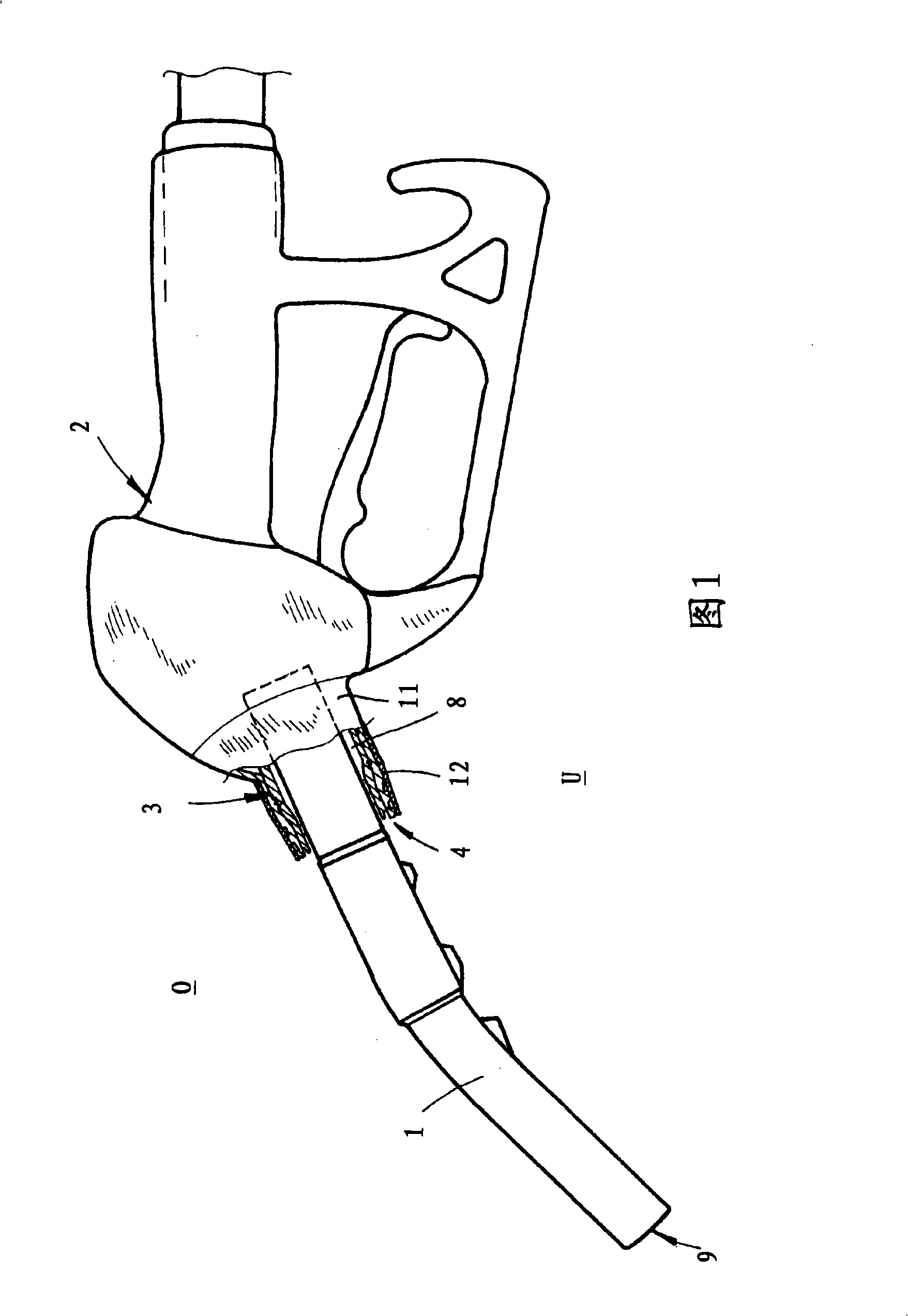
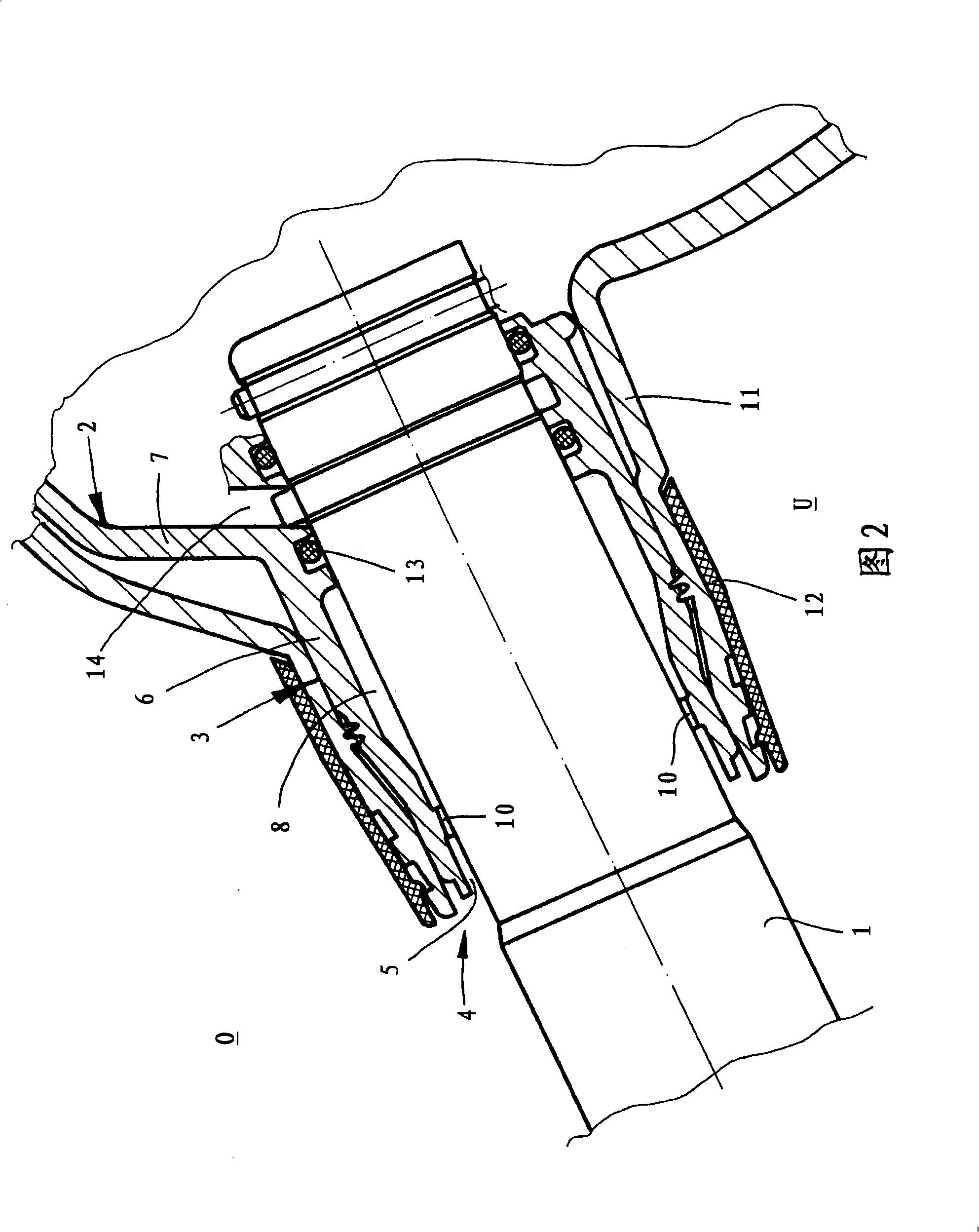
[0019]The accompanying drawing shows an automatic refueling valve for the fuel delivery hose of a petrol station fueling column supplying diesel fuel. The filling valve comprises a filling pipe 1 , a housing 2 with a housing connection 3 and a return drip collector 4 with a return channel 5 . Filler pipe 1 engages in housing socket 3 of housing 2 . The housing connection wall 6 is preferably, and in the exemplary embodiment, integrally connected to the housing wall 7 of the remaining housing 2 .

[0020] The return channel 5 of the return droplet collector 4 is connected to a receiving chamber of the return droplet collector 4 accommodated in the housing connection 3 . According to a particularly preferred embodiment, and in this exemplary embodiment according to the drawings, the oil return drop collector 4 with its return channel 5 and its receiving chamber 8 is completely integrated into the housing socket 3 . The return channel 5 is designed to be open toward the fuel-fe...


PUM


Abstract

The invention relates to an automatic oiling valve of fuel output tube of oil station column for supplying diesel fuel, comprising an oiling tube, a casing with casing connection tube and a circumfluence oil drop collector with a circumfluence groove, wherein the oiling tube is embedded into the casing connection tube, the circumfluence oil drop collector is assembled into the casing connection tube, and the circumfluence groove of the circumfluence oil drop collector is connected to one holding cavity of the circumfluence groove in the casing connection tube or casing.

Description

technical field [0001] The invention relates to an automatic refueling valve for a fuel outlet hose of a refueling column in a gas station for supplying diesel oil, comprising a refueling pipe, a housing with a housing connection and a return oil droplet collector with a return tank. The automatic refueling valve refers to such a refueling valve, which is suspended on the fuel tank of the vehicle to be refueled, especially when the fuel level in the fuel tank reaches the outlet of the refueling pipe, the refueling process is automatically interrupted. The return channel serves to collect residual fuel which flows back along the outside of the filler pipe which was wetted during refueling when the filler valve together with the filler pipe is moved upwards back into the filler column or suspended there accordingly. Within the scope of the present invention, diesel refers to fuels for diesel engines and also biodiesel, synthetic diesel, vegetable oils and / or fuels of similar vis...

Claims


Application Information

Patent Timeline
Patent Type & Authority Applications(China)
IPC IPC(8): B67D5/37B67D7/42
CPCB25B11/02B67D7/421
Inventor 卡尔海因茨·埃勒斯
Owner 凯.埃勒斯
Why Eureka
Try Eureka