Brake-energy recycling system for electric vehicle

A braking energy recovery and electric vehicle technology, applied in the direction of brakes, braking transmission devices, control devices, etc., can solve the problems of insufficient stability of the technology and high initial energy requirements, and achieve simple and easy layout, effective and stable transmission, and high efficiency high effect

Inactive Publication Date: 2015-10-28
FUJIAN UNIV OF TECH
View PDF8 Cites 0 Cited by
  • Summary
  • Abstract
  • Description
  • Claims
  • Application Information

AI Technical Summary

Problems solved by technology

It has high requirements for initial energy (torque speed), and the current technology is not stable enough, so it is mainly suitable for use on large vehicles

Method used


Image

  • Brake-energy recycling system for electric vehicle
  • Brake-energy recycling system for electric vehicle
  • Brake-energy recycling system for electric vehicle

Examples


specific Embodiment approach

[0028] A kind of specific implementation mode of the present invention is as follows:

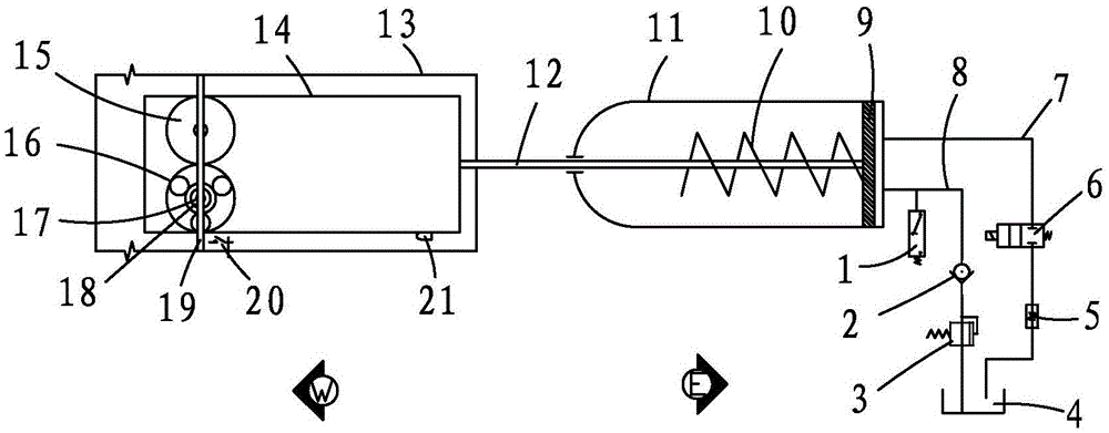
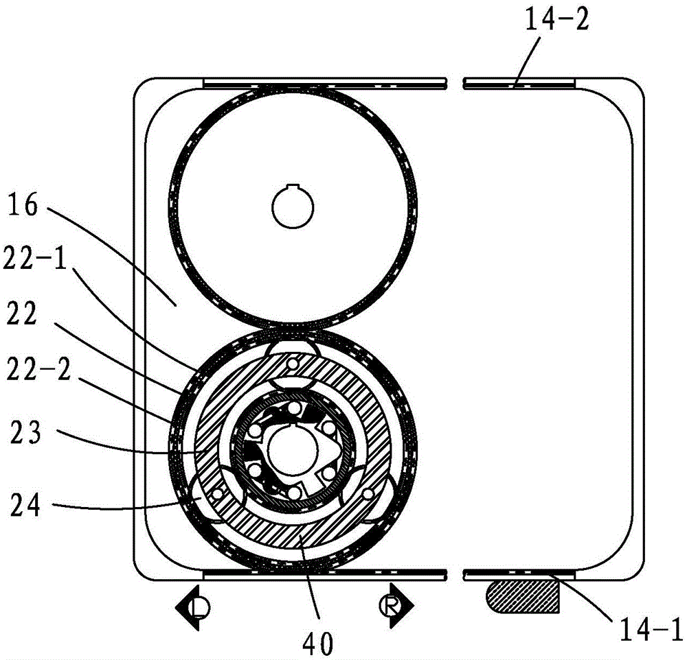
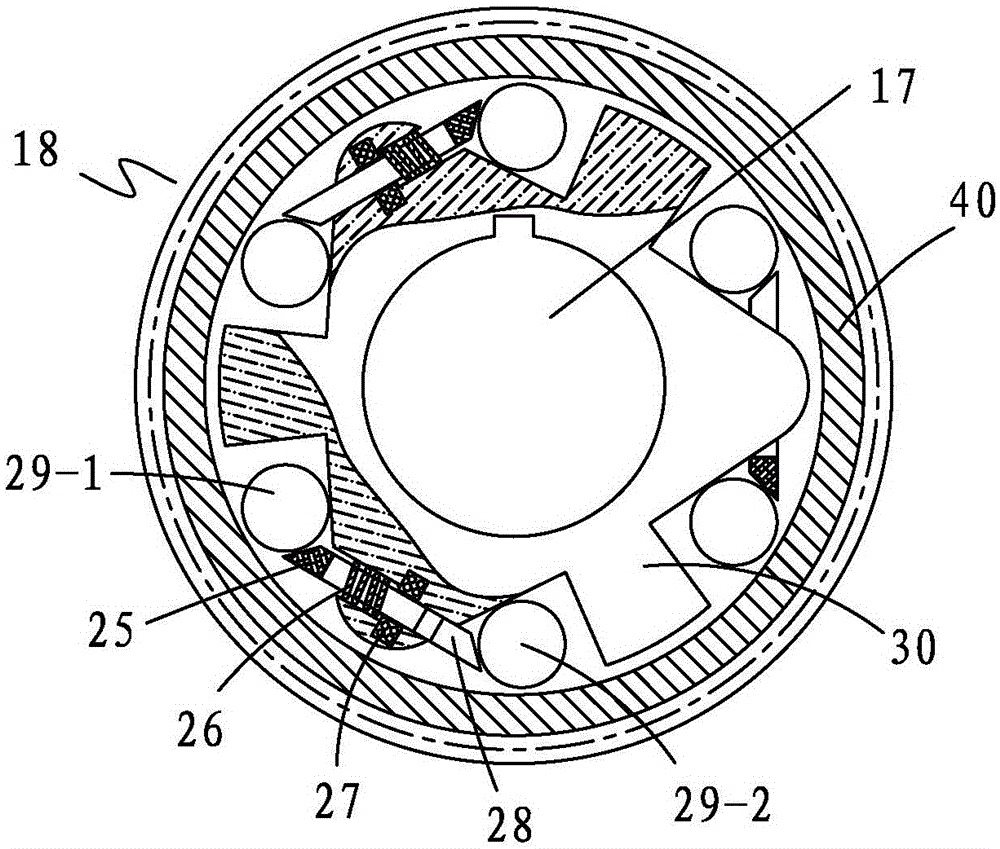
[0029] Such as Figures 1 to 5 As shown, its connection mode is: the two-way overrunning clutch 18 is connected with the drive shaft 17 of the vehicle drive wheel through a flat key, and the two-way overrunning clutch 18 is connected to the inner hole of the sun gear 40 of the planetary gear mechanism 16, and the sun gear 17 of the planetary gear mechanism 16 The wheel 40 is connected to the planetary gear 24 and then connected to the ring gear 22 internal teeth 22-1, and the ring gear internal teeth 22-1 and the ring gear external teeth 22-2 of the planetary gear mechanism 16 are respectively fixed on the inner ring of the ring gear 22 and the outer ring, the upper side of the ring gear outer teeth 22-2 is connected to the auxiliary gear 15 outer teeth, and the other lower side is connected to the lower rack 14-1 of the double rack frame 14, and the auxiliary gear 15 outer teeth are connec...


PUM


Abstract

The invention provides a brake-energy recycling system for an electric vehicle. The brake-energy recycling system comprises a planetary gear mechanism, an energy storage mechanism, a double-rack frame, a gear fixing rack and an auxiliary gear, wherein a two-way overrunning clutch is arranged in the planetary gear mechanism; one end part of the double-rack frame is connected to the energy storage mechanism; the planetary gear mechanism is meshed with the auxiliary gear; a lower rack and an upper rack are arranged in the double-rack frame; the upper rack is meshed with the auxiliary gear; the lower rack is meshed with the planetary gear mechanism; the gear fixing rack is used for fixing the planetary gear mechanism and the auxiliary gear to the electric vehicle, so that the mechanical energy can be sufficiently recycled.

Description

technical field [0001] The invention relates to an energy recovery and reuse system, in particular to an electric vehicle braking energy recovery and reuse system. Background technique [0002] In terms of energy storage for electric vehicles, hydraulic energy storage is used, and hydraulic transmission relies on the pressure of liquid in a sealed container to achieve motion and power transmission. The hydraulic transmission device is essentially an energy conversion device. He first converts mechanical energy into Hydraulic energy, and then convert the hydraulic energy into mechanical energy to do work, the conversion efficiency is low. Since the leakage of the working medium and the compressibility of the liquid will affect the accuracy of the movement of the actuator, the hydraulic transmission system cannot guarantee an accurate transmission ratio and cannot be used in the internal transmission chain with strict transmission ratio requirements. The hydraulic transmission...

Claims


Application Information

Patent Timeline
Patent Type & Authority Applications(China)
IPC IPC(8): B60K17/04B60K17/02B60T13/12
Inventor 李敏旭黄豪杰
Owner FUJIAN UNIV OF TECH
Why Eureka
Try Eureka