
Closed-cycle control system for digital dynamic force moment of DC motor

A DC motor and dynamic torque technology, applied in the field of control systems, can solve problems such as complex circuit structure, high cost, and limited frequency range of system capture

Inactive Publication Date: 2009-01-28
NANJING DALUGE HIGH TECH CO LTD +1
View PDF0 Cites 4 Cited by
  • Summary
  • Abstract
  • Description
  • Claims
  • Application Information

AI Technical Summary

Problems solved by technology

Although the phase-locked system can obtain high speed stabilization accuracy when locked, the system must be in an out-of-lock state when it is started, and the system capture has a frequency range limit
[0004] The circuits of the above two speed control systems use analog circuits or analog digital circuits, the circuit structure is complex and the cost is high

Method used


Image

  • Closed-cycle control system for digital dynamic force moment of DC motor
  • Closed-cycle control system for digital dynamic force moment of DC motor

Examples


Embodiment 1

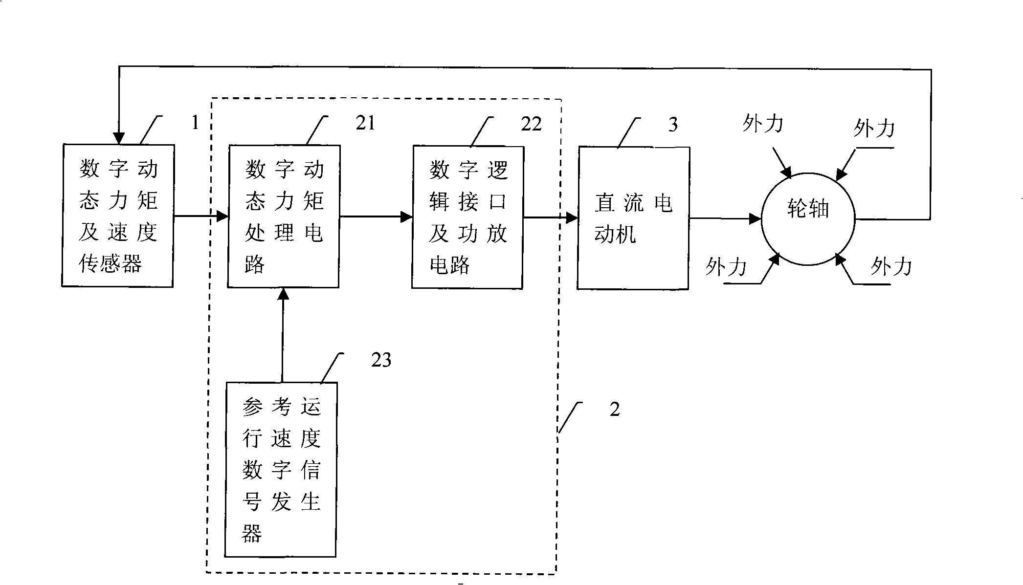
[0025] refer to figure 1 , figure 1 It is a block diagram of a DC motor digital closed-loop control system of the present invention, the DC motor digital closed-loop control system includes a digital sensor 1, a reference speed digital signal generator 23, a digital dynamic torque signal processing circuit 21, a digital logic interface and a power amplifier circuit 22 and a DC motor 3.

[0026] A digital sensor 1, which is coaxial with the motor 3, is used to transmit a dynamic digital pulse signal comprising real-time torque and speed information to the digital dynamic torque signal processing circuit 21;

[0027] The reference speed digital signal generator 23 is used to set the standard speed digital pulse signal of the DC motor, and output the pulse signal as a reference speed pulse signal to the digital dynamic torque signal processing circuit 21;

[0028] The digital dynamic torque signal processing circuit 21 is used to compare the positions of the reference speed pul...

Embodiment 2

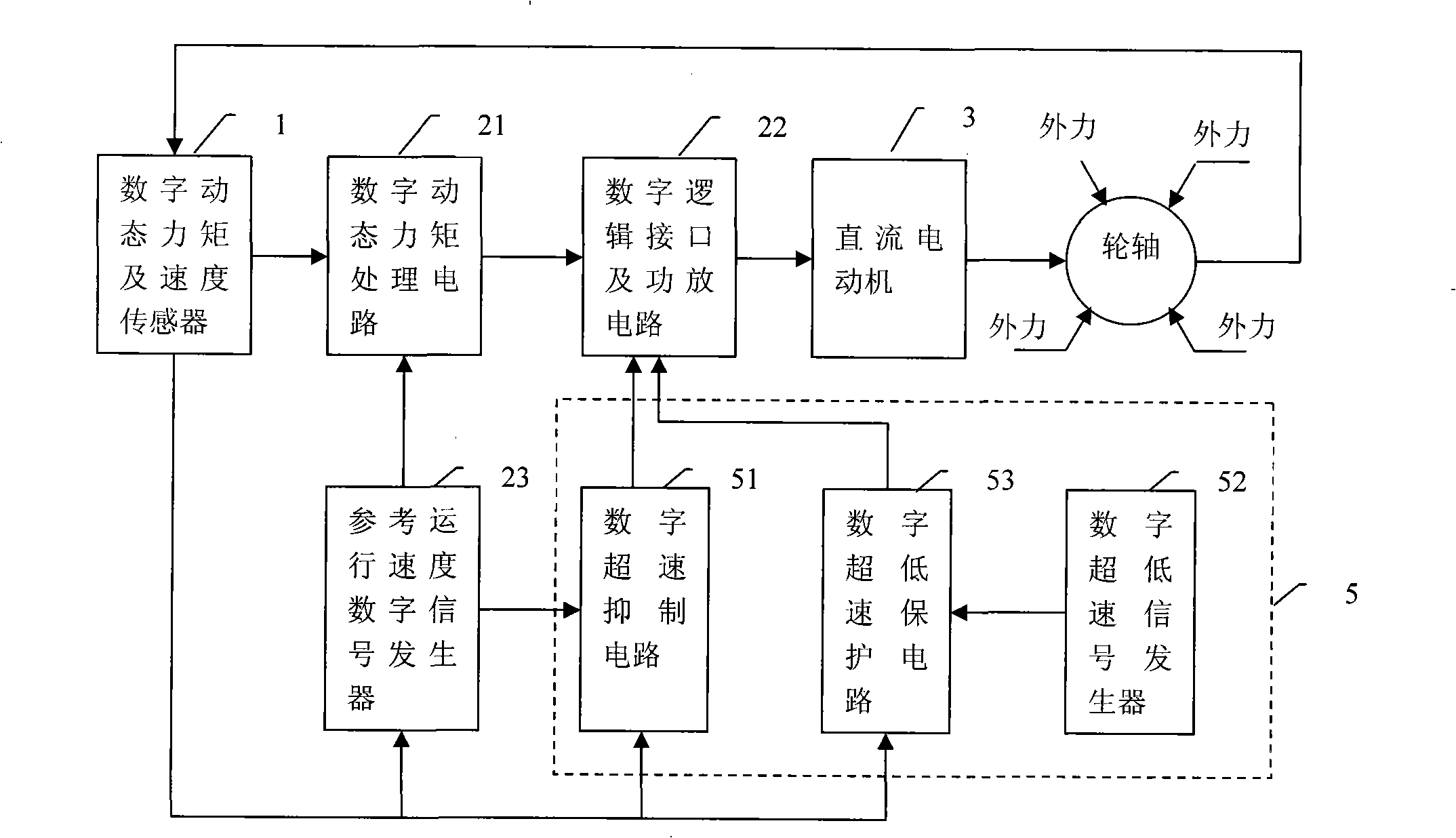
[0033] refer to figure 2 , figure 2 DC motor digital closed-loop control system structural block diagram, add protection circuit 5 on the structure of preceding example, protection circuit 5 comprises overspeed digital suppression circuit 51, ultra-low speed digital signal generator 52 and ultralow speed digital protection circuit 53; Overspeed suppression circuit 51, receiving The real-time speed pulse signal sent by the digital sensor 1 and the reference speed pulse signal sent by the reference speed signal generator 23 compare the real-time speed pulse signal with the preset speed pulse signal, and when the real-time speed is higher than the preset speed, the The monostable circuit continuously sends a short pulse width closing signal to the digital logic interface circuit 22, thereby suppressing the overspeed phenomenon and making the motor return to the normal running speed; the ultra-low speed digital signal generator 52 presets the ultra-low speed digital Pulse signa...


PUM


Abstract

The invention relates to a digital closed loop control system for a DC motor for realizing control by a dynamic moment. The invention aims to provide the digital closed loop control system for the DC motor with a simple structure, low cost, convenient debugging and good speed adjusting performance. The digital closed loop control system comprises a DC motor, a digital sensor, a reference speed digital signal generator, a digital dynamic moment signal processing circuit, a digital logic interface and a power amplifying circuit, wherein the digital sensor is used for sending a dynamic digital pulse signal containing the real-time moment dynamic change information and speed information to the digital dynamic moment signal processing circuit; the reference speed digital signal generator outputs a reference digital speed pulse signal to the dynamic digital moment signal processing circuit; the digital dynamic moment signal processing circuit is used for obtaining the vector of the dynamic moment variable and outputting and controlling the impulse width signal conducted by a power converter; and the digital logic interface and the power amplifying circuit are used for controlling a power tube to output corresponding width of the impulse so as to drive the DC motor.

Description

technical field [0001] The invention relates to a control system of a DC motor, in particular to a digital closed-loop control system of a DC motor controlled by dynamic torque. Background technique [0002] According to the principle and structure of the DC motor, the single closed-loop speed regulation system with current negative feedback cannot meet the rapid dynamic requirements of the system. To achieve fast and stable system performance, two signals of speed and current must be controlled. Among these two signals, the speed can be given manually and must be controlled during the whole process. The current signal is determined by the load during stable operation and cannot be given artificially. Only when there is an error between the speed and the given speed, it is correct It is controlled, and the control value at this time is only to prevent the current from exceeding the allowable maximum value, so that it cannot be added to the input terminal of a governor at the...

Claims


Application Information

Patent Timeline
IPC IPC(8): H02P7/00
Inventor 汪鸿洲
Owner NANJING DALUGE HIGH TECH CO LTD
Learn More