Ionization-based detection

A non-ionizing, ionizing source technology used in ionization-based detection to address issues such as noisy sensors, interference, high detector start-up or "fire" voltages

Inactive Publication Date: 2009-01-28
HONEYWELL INT INC
View PDF0 Cites 9 Cited by
  • Summary
  • Abstract
  • Description
  • Claims
  • Application Information

AI Technical Summary

Problems solved by technology

Some types of detectors used in this analyzer rely on radioactive sources which are of environmental concern
Additionally, some detectors used require high actuation or "firing" voltages, which will cause noise and interference with electronics or other adjacent sensors

Method used


Image

  • Ionization-based detection
  • Ionization-based detection
  • Ionization-based detection

Examples


Embodiment Construction

[0013] References in the specification to "an embodiment," "an embodiment," and "exemplary embodiment" mean that the illustrated embodiment includes a particular feature, structure, or characteristic, but that each embodiment does not necessarily include that particular feature, structure, or characteristic. structure or property. Furthermore, these terms do not necessarily refer to the same embodiment. Furthermore, when specific features, structures or characteristics are described in connection with an embodiment, it means that those characteristics, structures or characteristics can be related to other embodiments within the knowledge of those skilled in the art, whether or not it is clearly stated to explain.

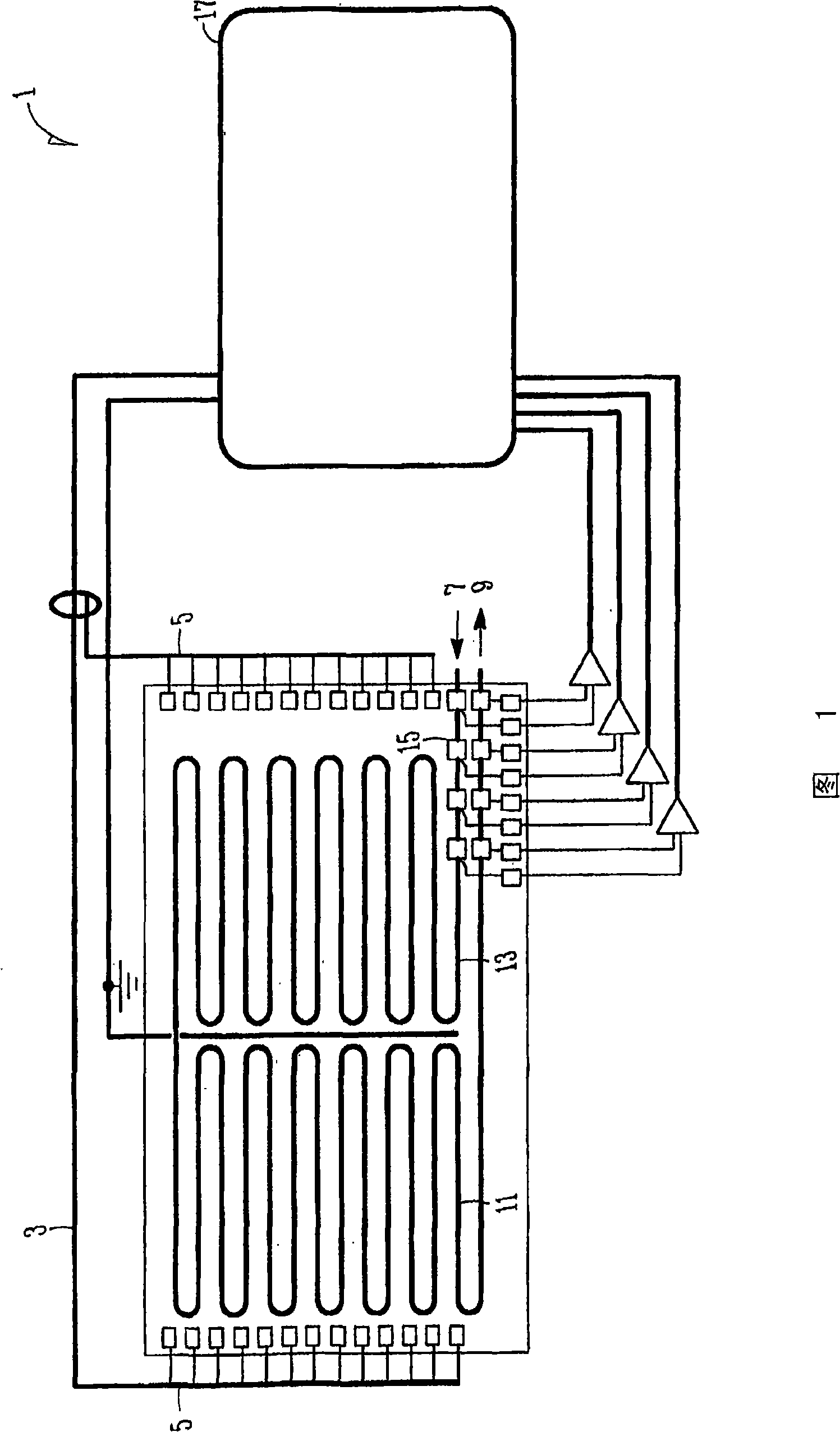
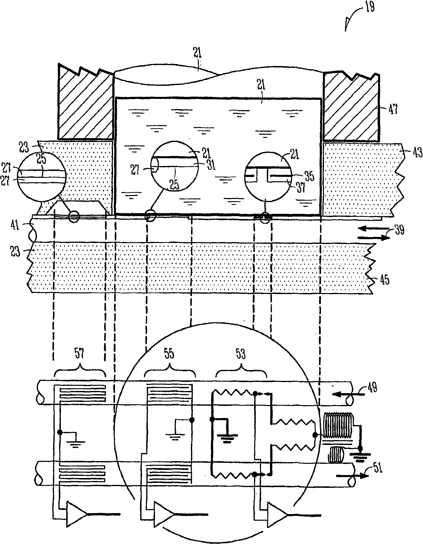
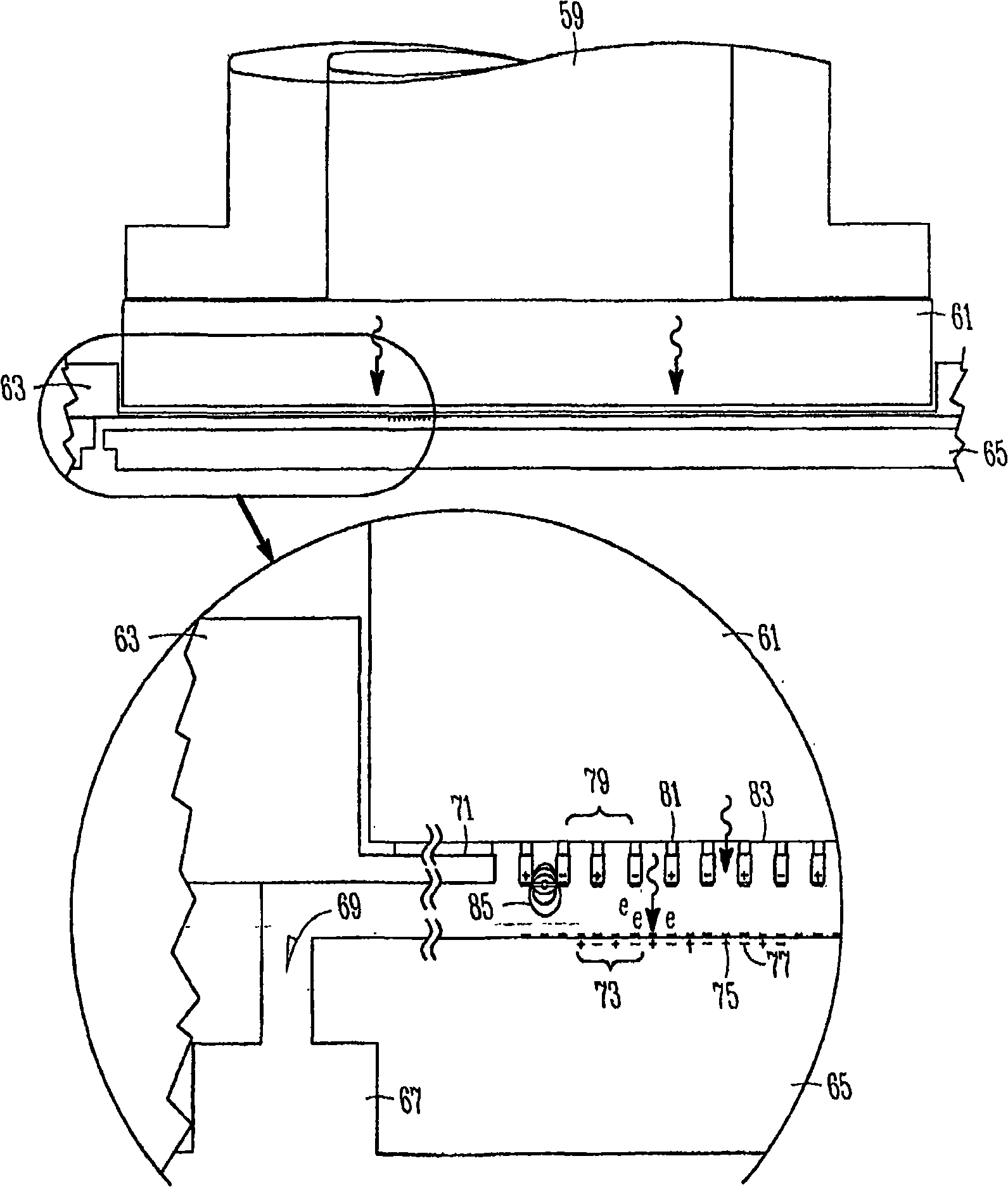
[0014] Embodiments of the present invention relate to multi-dimensional detector structures by integrating multiple detectors such as those based on thermal conductivity (TC), photoionization (PI), ion mobility (IM), electron capture (EC) and ion Capture Mass Spec...


PUM


Abstract

Embodiments of the present invention relate to detector structures for us in a micro gas analyzer, preferably in a differential setup. The detector structures may comprise one or more detector types, such as photo-ionization (PID), electron capture (ECD), ion mobility (IMS), differential mobility (DMS), ion-trap mass spectrometer (ITMS), in which all are provided with ions and electrons from one vacuum ultra violet (VUV) source. This source may also provide ions for ion-based gas pumps.

Description

[0001] related application [0002] This application claims priority to US Provisional Application Serial No. 60 / 681776, entitled Microfluidic Analyzers, filed May 17, 2005, which is incorporated herein by reference. technical field [0003] Embodiments of the invention relate to ionization-based detection for microanalyzers. More particularly, embodiments of the present invention relate to detector structures and detection methods for micro gas chromatography (GC). Background technique [0004] Micro-volume analyzers, such as micro-volume gas chromatographs, offer the versatility and adaptability of detection techniques not found in traditional analyzers. Because of their small size and portability, microanalyzers can perform laboratory processing in the field, in locations that are inaccessible to significantly larger conventional instruments, providing realistic results for many types of samples. Microanalyzers can have environmental or military applications, such as in...

Claims


Application Information

Patent Timeline
Patent Type & Authority Applications(China)
IPC IPC(8): G01N27/66G01N30/62G01N30/78G01N30/64G01N30/70G01N30/60G01N27/64G01N30/66G01N30/72G01N30/02
CPCG01N30/6095G01N2030/642G01N30/64G01N30/66G01N2030/645G01N30/78G01N30/70G01N27/624G01N27/622G01N2030/025G01N30/62G01N30/7206
Inventor U·邦内T·M·马塔K·M·纽斯托姆-佩特索
Owner HONEYWELL INT INC
Why Eureka
Try Eureka