Dielectric material treatment system and method of operating

a dielectric material and treatment system technology, applied in the field of dielectric material treatment system, can solve the problems of deterioration of mechanical strength, major limitation of interconnection delay, and affecting the operation of the system,

Inactive Publication Date: 2010-03-18
TOKYO ELECTRON LTD
View PDF63 Cites 322 Cited by
  • Summary
  • Abstract
  • Description
  • Claims
  • Application Information

AI Technical Summary

Benefits of technology

[0011]The invention relates to a system for treating a dielectric film and, more particularly, to a system for curing a low dielectric constant (low-k) dielectric film.

Problems solved by technology

As is known to those in the semiconductor art, interconnect delay is a major limiting factor in the drive to improve the speed and performance of integrated circuits (IC).
Low-k materials are less robust than more traditional silicon dioxide, and the mechanical strength deteriorates further with the introduction of porosity.
The porous low-k films can easily be damaged during plasma processing, thereby making desirable a mechanical strengthening process.
However, when processing porous dielectric films (such as ultra low-k films) with a high level of porosity, the degree of cross-linking achievable with thermal treatment (or thermal curing) is no longer sufficient to produce films of adequate strength for a robust interconnect structure.
Therefore, high temperatures and long curing times are required for typical low-k furnace curing.
But even with a high thermal budget, the lack of initiator generation in the thermal curing and the presence of a large amount of methyl termination in the as-deposited low-k film can make it very difficult to achieve the desired degree of cross-linking.

Method used


Image

  • Dielectric material treatment system and method of operating
  • Dielectric material treatment system and method of operating
  • Dielectric material treatment system and method of operating

Examples


Embodiment Construction

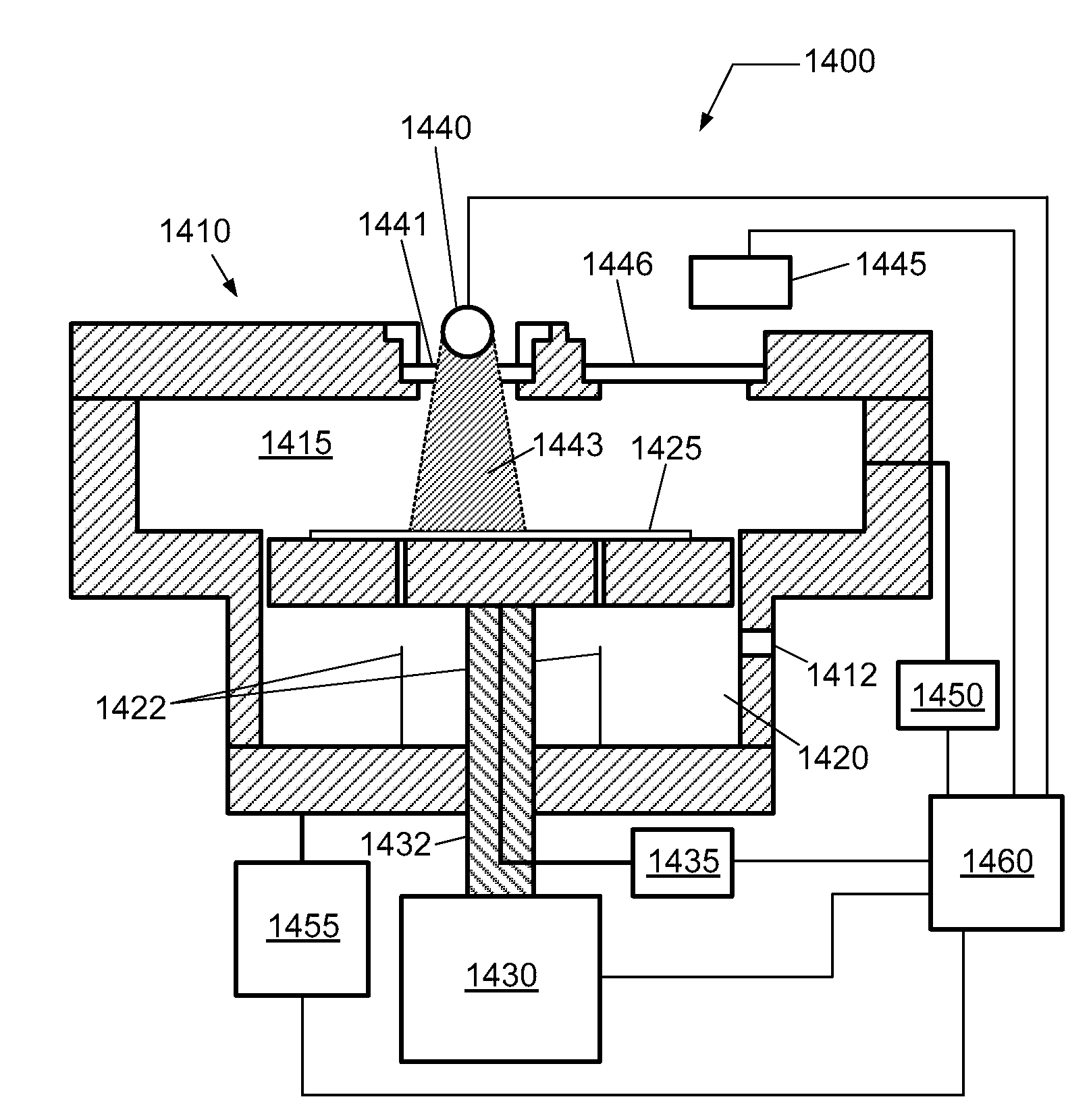
[0035]In the following description, in order to facilitate a thorough understanding of the invention and for purposes of explanation and not limitation, specific details are set forth, such as a particular geometry of the processing system and descriptions of various components and processes. However, it should be understood that the invention may be practiced in other embodiments that depart from these specific details.

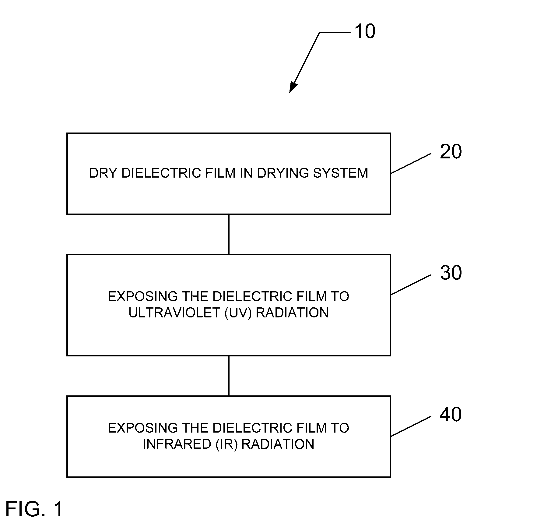
[0036]The inventors recognized that alternative curing methods address some of the deficiencies of thermal curing alone. For instance, alternative curing methods are more efficient in energy transfer, as compared to thermal curing processes, and the higher energy levels found in the form of energetic particles, such as accelerated electrons, ions, or neutrals, or in the form of energetic photons, can easily excite electrons in a low-k dielectric film, thus efficiently breaking chemical bonds and dissociating side groups. These alternative curing methods facilitate th...


PUM


Abstract

A system for curing a low dielectric constant (low-k) dielectric film on a substrate is described, wherein the dielectric constant of the low-k dielectric film is less than a value of approximately 4. The system comprises one or more process modules configured for exposing the low-k dielectric film to electromagnetic (EM) radiation, such as infrared (IR) radiation and ultraviolet (UV) radiation.

Description

CROSS-REFERENCE TO RELATED APPLICATIONS[0001]This application is related to pending U.S. patent application Ser. No. 11 / 269,581, entitled “MULTI-STEP SYSTEM AND METHOD FOR CURING A DIELECTRIC FILM”, filed on Nov. 9, 2005, and pending U.S. patent application Ser. No. 11 / 269,581, entitled “THERMAL PROCESSING SYSTEM FOR CURING DIELECTRIC FILMS”, filed on Sep. 8, 2006. Further, this application is related to co-pending U.S. patent application Ser. No. 12 / ______, entitled “DIELECTRIC TREATMENT MODULE USING SCANNING IR RADIATION SOURCE” (TDC-013), filed on even date herewith; co-pending U.S. patent application Ser. No. 12 / ______, entitled “IR LASER OPTICS SYSTEM FOR DIELECTRIC TREATMENT MODULE” (TDC-014), filed on even date herewith; and co-pending U.S. patent application Ser. No. 12 / ______, entitled “DIELECTRIC TREATMENT PLATFORM FOR DIELECTRIC FILM DEPOSITION AND CURING” (TDC-015), filed on even date herewith. The entire contents of these applications are herein incorporated by referenc...

Claims


Application Information

Patent Timeline
Patent Type & Authority Applications(United States)
IPC IPC(8): G21K5/00
CPCH01L21/268H01L21/67207H01L21/67184H01L21/67115
Inventor LIU, JUNJUNFAGUET, JACQUESLEE, ERIC M.TOMA, DOREL I.YUE, HONGYU
Owner TOKYO ELECTRON LTD
Why Eureka
Try Eureka