Multi-lens camera

a multi-lens, camera technology, applied in the field of cameras, can solve the problems of incontiguous pixels of each color, inability to produce high-quality images for both visible light and infrared light without mechanical changes, and the cost difference between small and large lenses is increased by scale. to achieve the effect of determining the boundary of objects

Inactive Publication Date: 2013-10-03
ZETTA RES & DEV - FORC SERIES
View PDF7 Cites 307 Cited by
  • Summary
  • Abstract
  • Description
  • Claims
  • Application Information

AI Technical Summary

Benefits of technology

[0072]Note that it is not necessary that the pixel resolution of the z-axis array match the pixel resolution of the associated photograph, as scaling is used in some embodiments to relate the pixels of the z-axis array to the pixels of the final image.
[0073]In one embodiment, the camera determines the distances of portions of the subject, and from that the slope of portions of the subject, by the use of two pair of sub-cameras, one pair arranged vertically and one pair arranged horizontally. The parallax between two image portions from two sub-camera pairs are compared. Deviations between the two image portions indicates a distinct boundary between a foreground object and a background object. The deviations from both sub-cameras pairs are combined, for example by summing or taking a maximum, in order to identify a complete boundary around a foreground object. This capability does not exist in stereo camera prior art. The width (say, in pixels) of the deviation determines the distance between the foreground object and the background. The direction of shift of the object between the two images determines which side of the deviation is foreground and which side is background. Typically, 2D correlation on the entire image, areas within the image, and sub-areas within the area, is used to determine the reference alignment (at infinity) and the amount of deviation at each point in the photograph. Determining the boundaries of objects is enhanced by the use of line-following algorithms, color matching, texture matching, and noise matching, as is known in the art. In addition, the comparison of brightness between a flash image and a natural-light image (taken sequentially but at almost the same instant in time) is used in some embodiments to assist in determining distance, angle, and slope of objects in the subject area. Some objects, such as faces, are determined by matching characteristics (including, shape, color, texture, and nearby objects) to a library of known objects. In addition, in some embodiments, motion of an object or sub-area between two frames taken at different times is used to enhance subject (the moving portion against a still background) isolation.

Problems solved by technology

In addition, smaller lenses are sold and manufactured in higher volume than large lenses, so economies of scale add to the cost difference between small and large lenses.
A disadvantage of this filter is that the pixels for each color are not contiguous.
Traditional cameras cannot product high quality images for both visible light and infrared light without mechanical changes, such as changing the focal-length of the lens or changing the filter(s) in the optical path.

Method used


Image

  • Multi-lens camera
  • Multi-lens camera
  • Multi-lens camera

Examples


Embodiment Construction

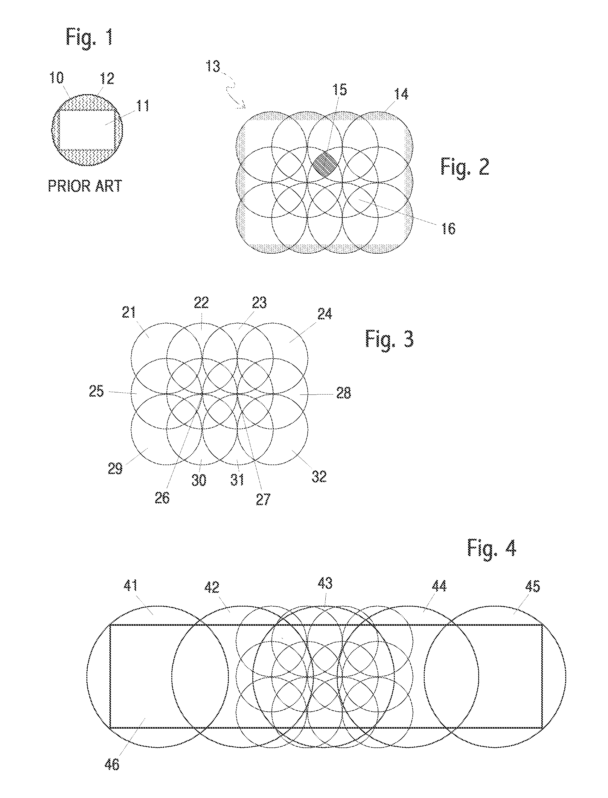
[0094]FIG. 1 shows prior art with a round image area in the image plane 10 and a portion of that area used by a rectangular sensor 11. The filled area 12 shows the “wasted” portion of the image area created by the lens but not used by the sensor and not available to the user of the camera.

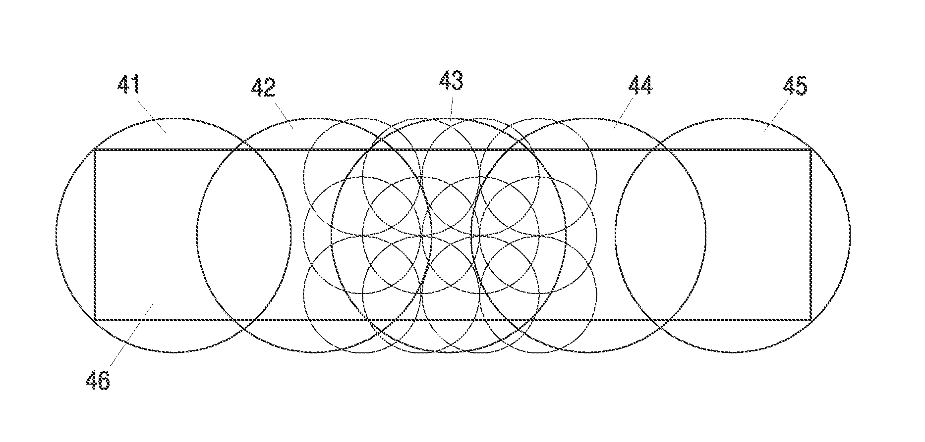
[0095]FIG. 2 shows one embodiment with a four by three array of lenses creating an approximately rectangular image area 13 in the effective computed image plane of the camera. An exactly rectangular region is shown inside the shaded area 14. Note that this area shown in this Figure is a virtual image plane, as the actual sensors for the twelve lenses are not overlapping as the circles in this Figure. The twelve circles in this Figure represent the imaging areas in a final photograph where each circle is the available portion of the final photograph from one lens / sensor pair. This Figure shows how the twelve images would be overlapped to create the effective final rectangular image inside the shaded...


PUM

PropertyMeasurementUnit
sizeaaaaaaaaaa
Wavelengthsaaaaaaaaaa

Abstract

A camera with multiple lenses and multiple sensors wherein each lens/sensor pair generates a sub-image of a final photograph or video. Different embodiments include: manufacturing all lenses as a single component; manufacturing all sensors as one piece of silicon; different lenses incorporate filters for different wavelengths, including IR and UV; non-circular lenses; different lenses are different focal lengths; different lenses focus at different distances; selection of sharpest sub-image; blurring of selected sub-images; different lens/sensor pairs have different exposures; selection of optimum exposure sub-images; identification of distinct objects based on distance; stereo imaging in more than one axis; and dynamic optical center-line calibration.

Description

FIELD OF THE INVENTION[0001]The field of this invention is cameras. More specifically, the field of this invention is cameras with multiple lenses.BACKGROUND OF THE INVENTION[0002]A traditional camera consists of one lens and one generally planer image receiving area. For many years, the image receiving area has comprised photosensitive film. In more recent years, most cameras have used an electronic image sensor, such as CCD or CMOS sensors. These sensors are traditionally rectangular, often having an aspect ratio of about 4:5 or 4:6. Common sensor sizes include: 35 mm “full frame,” APS-H, APS-C, “Four Thirds,” 1 / 1.6, 1 / 1.8, and 1 / 2.5 inch, and many others.[0003]Lenses for the simplest of cameras may be a single element of glass or plastic. Lenses for most cameras consist of multiple elements to reduce the various distortions and aberrations caused by a single lens.[0004]The cost of manufacturing lenses rises at the rate of at least the cube of the diameter of the lens since the vo...

Claims


Application Information

Patent Timeline
Patent Type & Authority Applications(United States)
IPC IPC(8): H04N5/33H04N5/228B23Q17/00H04N5/76
CPCH04N13/0242H04N9/8042H04N5/2254Y10T29/49764H04N5/232H04N17/002H04N5/2258H04N13/243H04N23/45
Inventor BETTS-LACROIX, JONATHAN N.
Owner ZETTA RES & DEV - FORC SERIES
Why Eureka
Try Eureka