Spark plug

a plug and spark plug technology, applied in the field of spark plugs, can solve the problems of difficulty in reducing the diameter reducing the voltage resistance of the center electrode, and simultaneously achieving the improvement of voltage resistance, so as to achieve the suppression of side sparking, side sparking is further suppressed, and the voltage resistance of the insulator improves.

Active Publication Date: 2016-08-11
NGK SPARK PLUG CO LTD
View PDF1 Cites 2 Cited by
  • Summary
  • Abstract
  • Description
  • Claims
  • Application Information

AI Technical Summary

Benefits of technology

[0012](3) In accordance with a third aspect of the present invention, there is provided a spark plug according to the above mode, wherein a position at, with respect to the direction along the axis line, a front end of the first cylindrical portion may be located on the front end side with respect to a position at, with respect to the direction along the axis line, a front end of a surface of the shelf portion opposing the first cylindrical portion. According to this mode, voltage resistance of the insulator improves at the front end position of the opposing surface. This is because the position of the opposing surface and the position of the truncated cone-shaped portion are misaligned in the direction along the axis line, and certain thickness can be ensured for the insulator at the position opposing the opposing surface.
[0013](4) In accordance with a fourth aspect of the present invention, there is provided a spark plug according to the above mode, wherein a position at, with respect to the direction along the axis line, a rear end of the second cylindrical portion may be located toward the rear end side by a distance not smaller than 1.5 mm from a position of a front end surface of the metal shell. According to this mode, side sparking is further suppressed. In this mode, the boundary between the second cylindrical portion and the truncated cone-shaped portion is located toward the rear end side by a distance not smaller than 1.5 mm from the position of the front end surface of the metal shell. Since fouling of the insulator associated with combustion within a combustion chamber occurs more easily when the outer diameter of the insulator is larger, fouling occurs more easily near the boundary or toward the rear end side from the boundary. Side sparking is induced at a part where fouling has occurred. Thus, as in this mode, side sparking is further suppressed by separating, by a distance not smaller than 1.5 mm, the part where fouling occurs easily and the front end surface of the metal shell where, by nature, side sparking occurs easily.
[0014](5) In accordance with a fifth aspect of the present invention, there is provided a spark plug according to the above mode, wherein a length of the second cylindrical portion in the direction along the axis line may be not smaller than 4 mm, and an area, in a cross section including the axis line, of one side of a padded part surrounded by a straight line at a front end side of the truncated cone-shaped portion, a straight line extended from the second cylindrical portion, and an outer diameter line of the insulator, may be 0.02 mm2. According to this mode, breakage of the insulator is suppressed even when the second cylindrical portion is long (not smaller than 4 mm). A phenomenon of high pressure being generated in a combustion chamber is known when an engine with a high compression ratio is used. When such a high pressure is generated, a large force is applied on the second cylindrical portion, and breakage easily occurs at the boundary between the second cylindrical portion and the truncated cone-shaped portion. Thus, the breakage occurs more easily when the second cylindrical portion is longer. By forming the padded part having a cross-sectional area as in this mode, the boundary is reinforced and the above described advantageous effect can be obtained.
[0015](6) In accordance with a sixth aspect of the present invention, there is provided a spark plug according to the above mode, wherein an external thread may be formed on an outer circumference of the metal shell, and a nominal diameter of the external thread may be M14. According to this mode, oxidation of the center electrode can be suppressed even with a strict condition for oxidation of the center electrode such as the nominal diameter of the external thread being M14. When the diameter of the center electrode is small and the nominal diameter of the external thread is M14, the volume of the space between the outer circumference of the insulator and the inner circumference of the metal shell becomes large. When the volume of this space becomes large, the heat capacity of gas within the space becomes large. As a result, the temperature of the center electrode rises easily, leading to acceleration of oxidation of the center electrode. However, with this mode, since I / E described above is set appropriately, oxidation of the center electrode can be suppressed.
[0016](7) In accordance with a seventh aspect of the present invention, there is provided a spark plug according to the above mode, wherein the spark plug may be used in at least one of an engine with a supercharger and having a compression ratio of not lower than 9.5, or a natural air intake engine having a compression ratio of not lower than 11. According to this mode, the above described advantageous effect can be obtained when the spark plug is used in any one of an engine with a supercharger and having a compression ratio of not lower than 9.5, and a natural air intake engine having a compression ratio of not lower than 11.

Problems solved by technology

Thus, reducing the diameter of the center electrode has been conventionally difficult.
However, an attempt to ensure certain thickness of the insulator while reducing the outer diameter of the insulator results in thinning of the center electrode disposed inside the insulator and causes the above described problem.
Since the above described dilemma has existed conventionally, simultaneously achieving improvement in voltage resistance, suppression of oxidation of the center electrode, and suppression of side sparking has been difficult.

Method used


Image

  • Spark plug
  • Spark plug
  • Spark plug

Examples


Embodiment Construction

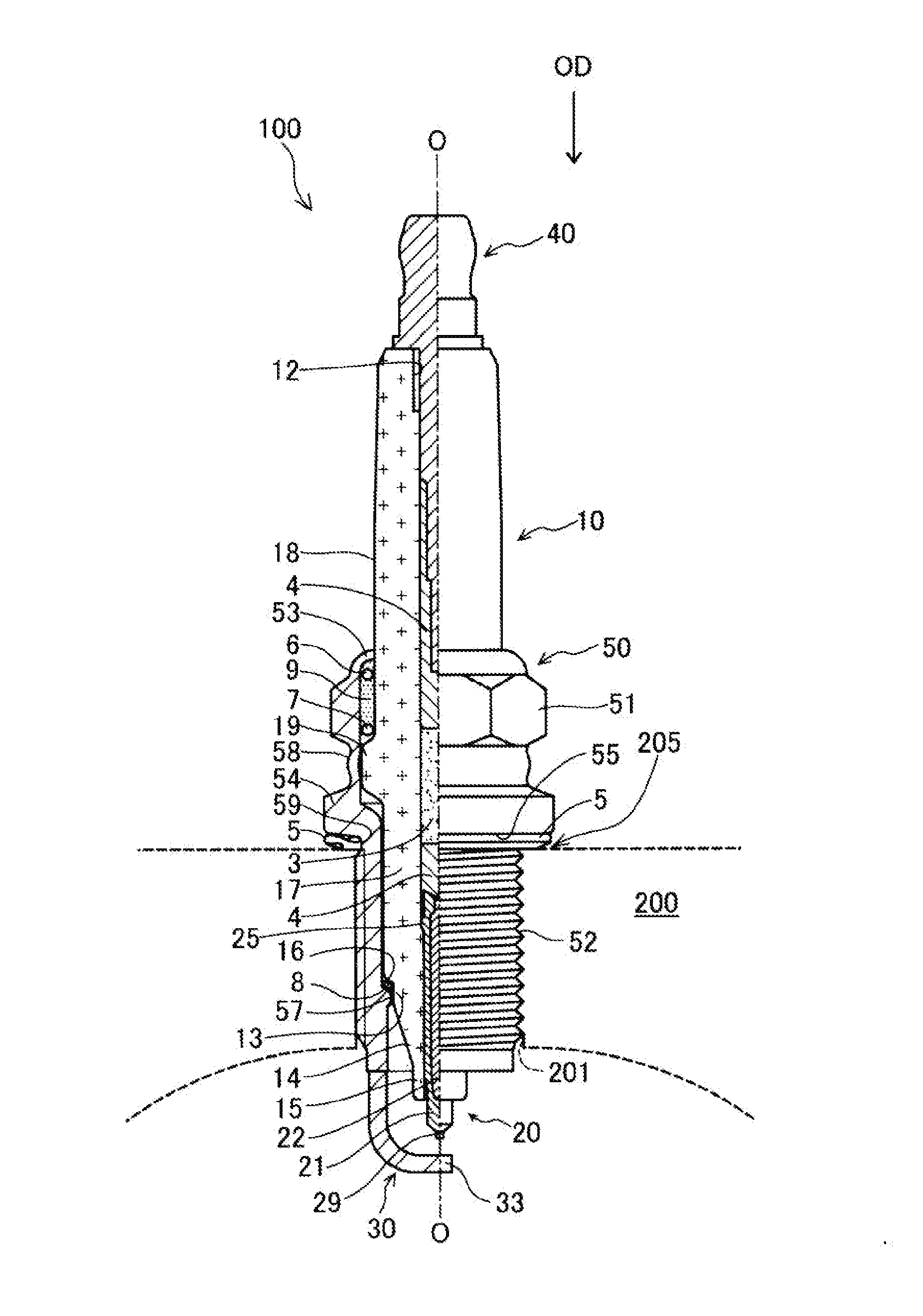
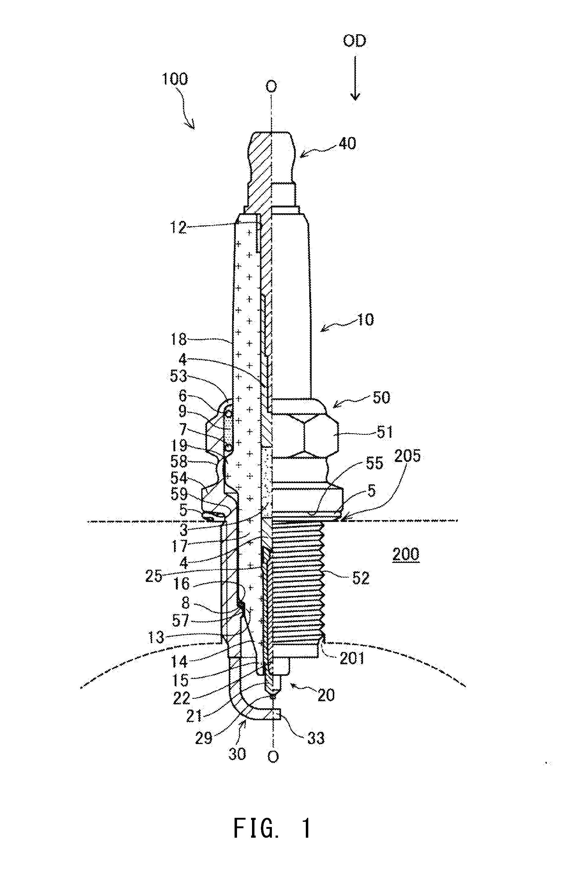
[0030]FIG. 1 is a partial cross-sectional view showing a spark plug 100. In the following, an axis line direction OD shown in FIG. 1 is defined as up-down direction in the drawing, and the lower side is defined as the front end side of the spark plug and the upper side is defined as the rear end side of the spark plug in the description. In FIG. 1, the exterior view of the spark plug 100 is shown on the right side of an axis line O, and a cross section of the spark plug 100 is shown on the left side of the axis line O.

[0031]The spark plug 100 is a device that is to be attached to an engine head 200 of a gasoline engine, and ignites an air-fuel mixture within a combustion chamber by causing spark discharge between electrodes at the front end.

[0032]The spark plug 100 includes a ceramic insulator 10, a center electrode 20, a ground electrode 30, a metal terminal 40, and a metal shell 50. The ceramic insulator 10 is a member that functions as an insulator, and has an axial hole 12 that ...


PUM


Abstract

A spark plug includes an insulator and a center electrode. The insulator includes: a first cylindrical portion; a truncated cone-shaped portion whose outer diameter reduces toward a front end side; and a second cylindrical portion formed at a front end side of the truncated cone-shaped portion. A diameter C of the center electrode is not larger than 2.2 mm. A total I of a volume of the truncated cone-shaped portion and a volume of the second cylindrical portion, a volume E of the center electrode from a position at a rear end of the truncated cone-shaped portion to a position at a front end of the second cylindrical portion, and the diameter C satisfy I/E≧4.2333C2−19.79C+24.869.

Description

FIELD OF THE INVENTION[0001]The present invention relates to a spark plug.BACKGROUND OF THE INVENTION[0002]A general spark plug includes a metal shell, a center electrode, and an insulator. Known shapes of the insulator include one that has, sequentially from a rear end side, a first cylindrical portion, a truncated cone-shaped portion, and a second cylindrical portion whose outer diameter is smaller than that of the first cylindrical portion. The first cylindrical portion is a cylindrical part formed inside the metal shell. The truncated cone-shaped portion is a part that is formed on a front end side of the first cylindrical portion and whose outer diameter becomes smaller toward the front end side. The second cylindrical portion is a part that is formed on the front end side of the truncated cone-shaped portion and whose at least one portion projects out from a front end surface of the metal shell. The first cylindrical portion, the truncated cone-shaped portion, and the second c...

Claims


Application Information

Patent Timeline
Patent Type & Authority Applications(United States)
IPC IPC(8): H01T13/20
CPCH01T13/20F02P13/00H01T13/36H01T13/34H01T13/16
Inventor FUKUZAWA, REIMONKUKI, HIROAKI
Owner NGK SPARK PLUG CO LTD
Why Eureka
Try Eureka