Process for sealing electro-optic displays

a technology of electro-optic displays and sealing processes, which is applied in the manufacture of electrode systems, electric discharge tubes/lamps, instruments, etc., can solve the problems of inadequate service life of these displays, preventing their widespread use, and gas-based electrophoretic media being susceptible to the same types of problems

Active Publication Date: 2006-07-11
E INK CORPORATION
View PDF188 Cites 261 Cited by
  • Summary
  • Abstract
  • Description
  • Claims
  • Application Information

AI Technical Summary

Problems solved by technology

Nevertheless, problems with the long-term image quality of these displays have prevented their widespread usage.
For example, particles that make up electrophoretic displays tend to settle, resulting in inadequate service-life for these displays.
Such gas-based electrophoretic media appear to be susceptible to the same types of problems due to particle settling as liquid-based electrophoretic media, when the media are used in an orientation which permits such settling, for example in a sign where the medium is disposed in a vertical plane.
Indeed, particle settling appears to be a more serious problem in gas-based electrophoretic media than in liquid-based ones, since the lower viscosity of gaseous suspending fluids as compared with liquid ones allows more rapid settling of the electrophoretic particles.
However, vacuum lamination of the two parts of an electro-optic display in this manner imposes stringent requirements upon the lamination adhesive used, as described in U.S. Patent Applications Publication Nos. 2003 / 0011867 (now U.S. Pat. No. 6,657,772) and 2003 / 0025855, especially in the case of a display using an encapsulated electrophoretic medium.
The lamination adhesive must have adequate flow properties at the lamination temperature to ensure high quality lamination, and in this regard, the demands of laminating encapsulated electrophoretic and some other types of electro-optic media are unusually difficult; the lamination has be conducted at a temperature of not more than about 130° C. since the medium cannot be exposed to substantially higher temperatures without damage, but the flow of the adhesive must cope with the relatively uneven surface of the capsule-containing layer, the surface of which is rendered irregular by the underlying capsules.
There are only a limited number of commercially available edge sealing materials which have all the properties required for use in such an electro-optic display, and most of these materials are cured by ultra-violet radiation.
However, in the preferred display shown in the drawing, and in similar displays in which the electro-optic medium is covered by a UV-absorbing protective layer, the presence of the protective layer, which is essentially opaque to UV radiation, renders it difficult to cure the sealing material.
In the preferred display shown in the drawing, in practice it is necessary to cure the sealing material by irradiating it from the side, which requires expensive capital equipment and requires large radiation penetration depths (several millimeters in typical cases).

Method used


Image

  • Process for sealing electro-optic displays
  • Process for sealing electro-optic displays

Examples


Embodiment Construction

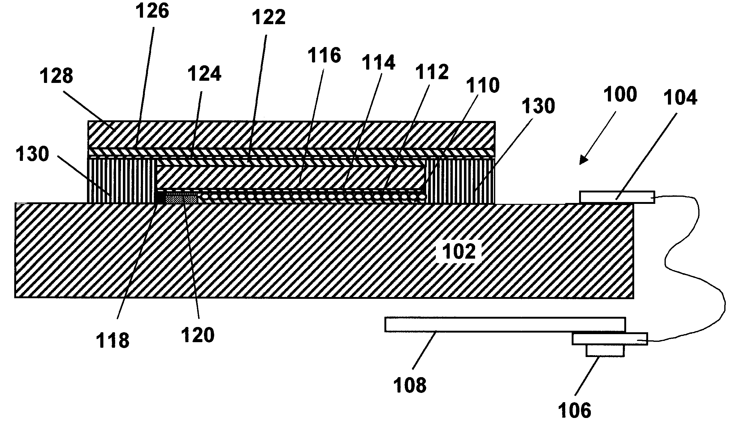
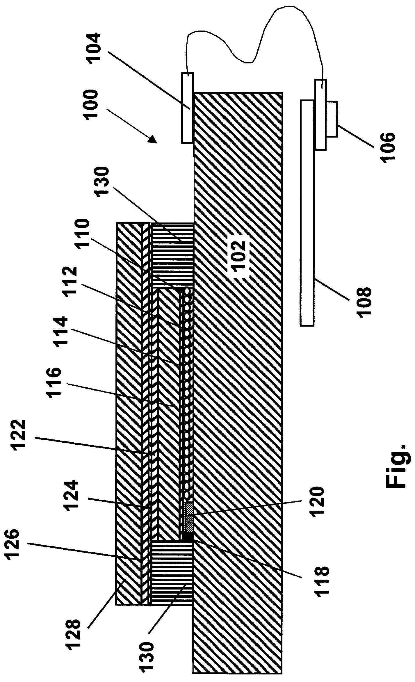
[0038]As already mentioned, the present invention provides a process for providing an edge seal in an electro-optic display. The display comprises a backplane; a layer of electro-optic material disposed adjacent the backplane; and a protective layer capable of absorbing ultra-violet (UV) radiation and disposed on the opposed side of the layer of electro-optic material from the backplane. The protective layer extends beyond the edge of the layer of electro-optic material, thereby defining a peripheral region in which a gap exists between the protective layer and the backplane. To form the edge seal, there is placed in the gap an uncured edge sealing material curable by radiation transmitted by the protective layer, and radiation effective to cure the edge sealing material is transmitted through the protective layer, thereby curing the edge sealing material and forming an edge seal in the gap.

[0039]Thus, in accordance with this invention, the edge seal is formed from a edge sealing ma...


PUM

PropertyMeasurementUnit
wavelengthaaaaaaaaaa

Abstract

An electro-optic display (100) comprising a backplane (102), a layer (112) of electro-optic material and a protective layer (128) capable of absorbing ultra-violet radiation and disposed on the opposed side of the layer (112) of electro-optic material from the backplane (102), is provided with an edge seal (130). The protective layer (128) extends beyond the layer (112) of electro-optic material, thus leaving a peripheral gap between the protective layer (128) and the backplane (102). To form the edge seal (130) an uncured edge sealing material curable by radiation transmitted by the protective layer (128) is placed in the gap and cured by transmitting radiation through the protective layer (128).

Description

REFERENCE TO RELATED APPLICATIONS[0001]This application claims benefit of Provisional Application Ser. No. 60 / 481,903, filed Jan. 16, 2004.[0002]This invention is related to copending application Ser. No. 10 / 249,957, filed May 22, 2003 (Publication No. 2004 / 0027327), and to copending application Ser. No. 10 / 605,024, filed Sep. 2, 2003 (Publication No. 2004 / 0155857). The entire disclosures of these two copending applications, and of all U.S. patents and published and copending applications referred to below, are also herein incorporated by reference.BACKGROUND OF INVENTION[0003]This invention relates to a process for sealing electro-optic displays; this process is especially, although not exclusively, intended for use in sealing such displays using encapsulated electrophoretic media. However, the invention can also make use of various other types of electro-optic displays which use an electro-optic medium which is solid, in the sense that it has solid external surfaces, although the ...

Claims


Application Information

Patent Timeline
Patent Type & Authority Patents(United States)
IPC IPC(8): G02B26/00G02F1/1335G02F1/1339G02F1/167G02F1/1679G09G3/34
CPCG02F1/133509G02F1/167G02F1/1339G02F2201/086G02F1/1679
Inventor O'NEIL, STEVEN J.DUTHALER, GREGG M.
Owner E INK CORPORATION
Why Eureka
Try Eureka