
Vacuum generating unit

一种产生单元、真空的技术,应用在泵元件、吸杯、连接构件等方向,能够解决气压供给阀不可能转换到阀关闭状态、不能进行工件、保持等问题

Active Publication Date: 2009-02-04
SMC CORP
View PDF2 Cites 6 Cited by
  • Summary
  • Abstract
  • Description
  • Claims
  • Application Information

AI Technical Summary

Problems solved by technology

Based on this, for example, in the case of using the vacuum generating unit for a pump system or the like that supplies vacuum pressure from the outside, since the diffuser is not provided, it is impossible to switch the air pressure supply valve to the valve closed state
[0006] In addition, in this type of vacuum generating unit, since the suction under the suction force of the workpiece is performed, the supply amount of compressed air is reduced while the workpiece is held, and communication with the atmosphere occurs through the air pressure supply valve in the valve-open state, Therefore, the workpiece cannot be held

Method used


Image

  • Vacuum generating unit
  • Vacuum generating unit
  • Vacuum generating unit

Examples


Embodiment Construction

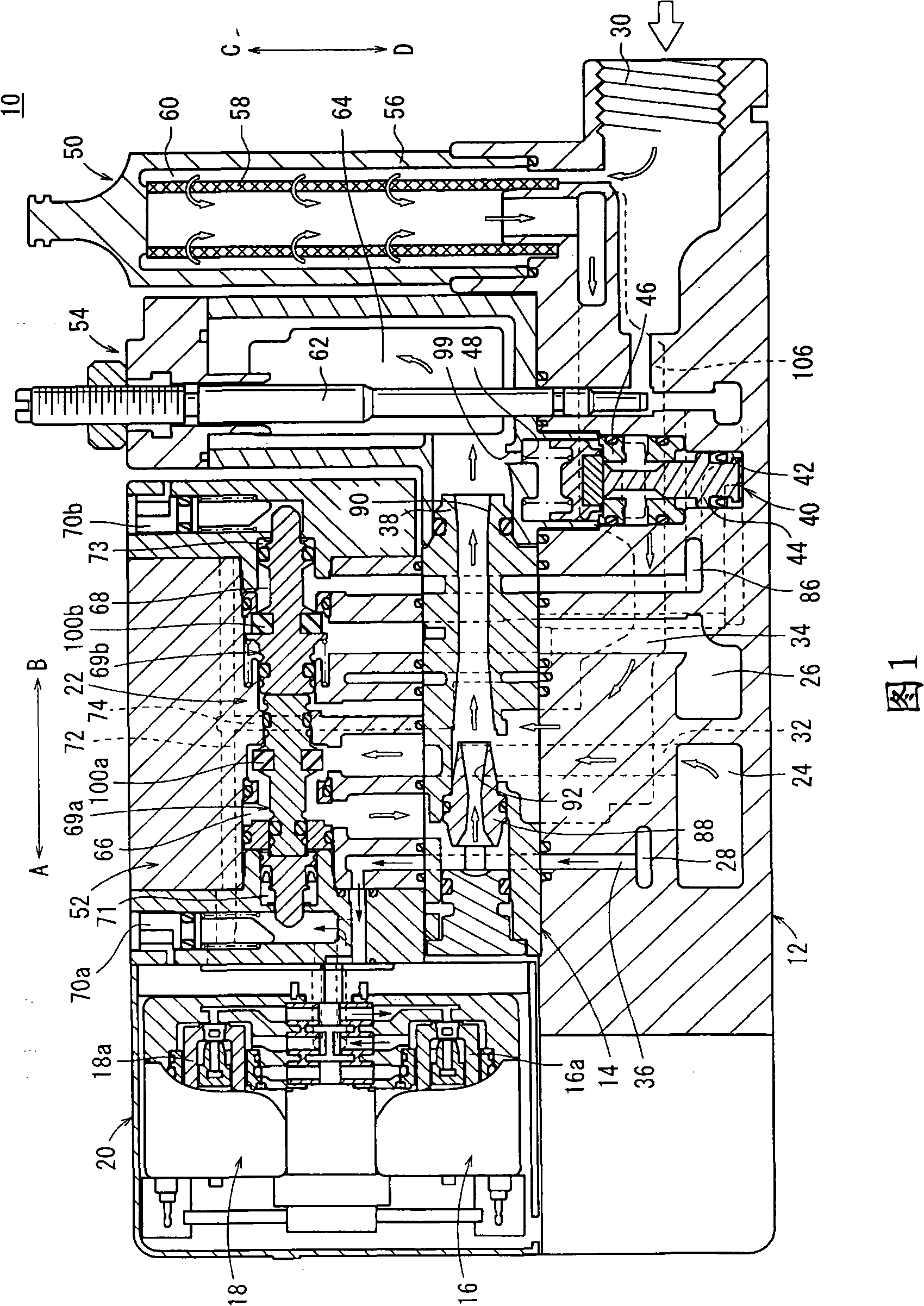
[0019] In FIG. 1, reference numeral 10 denotes a vacuum generating unit of an embodiment of the present invention.

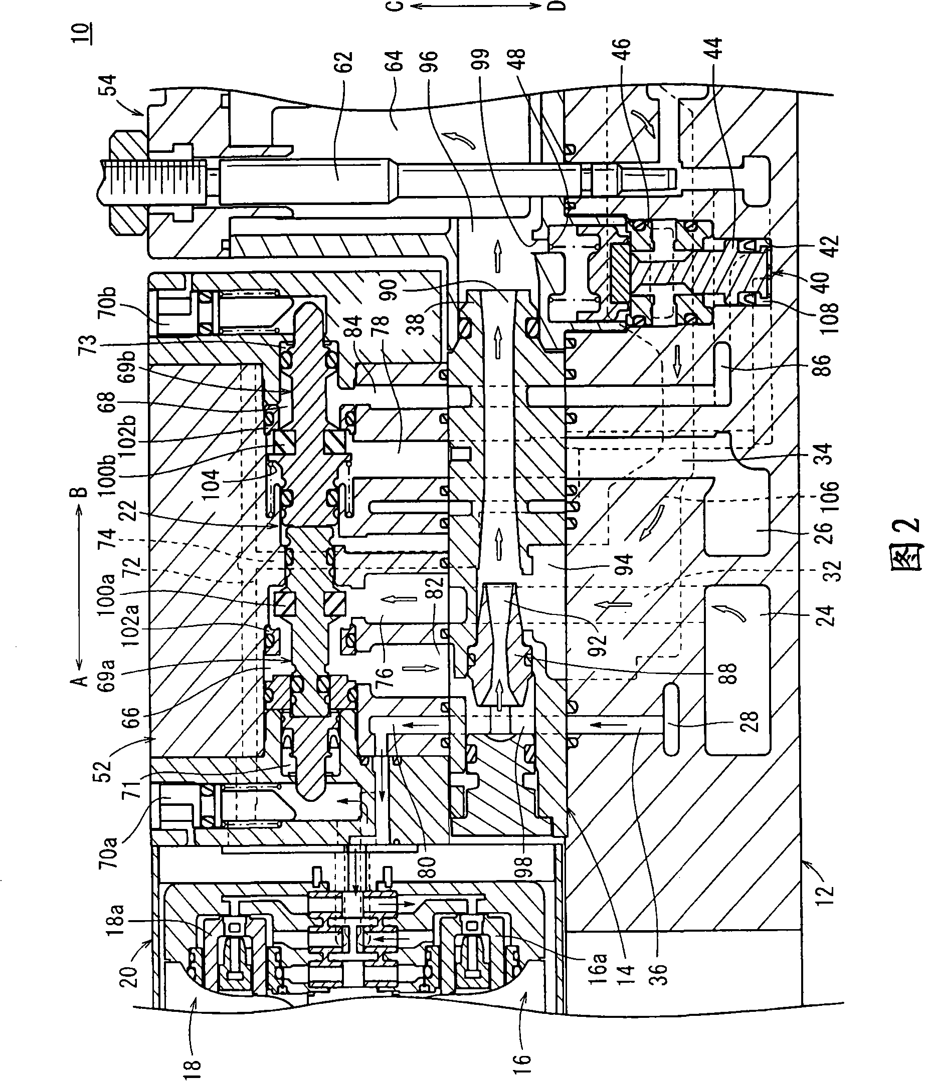
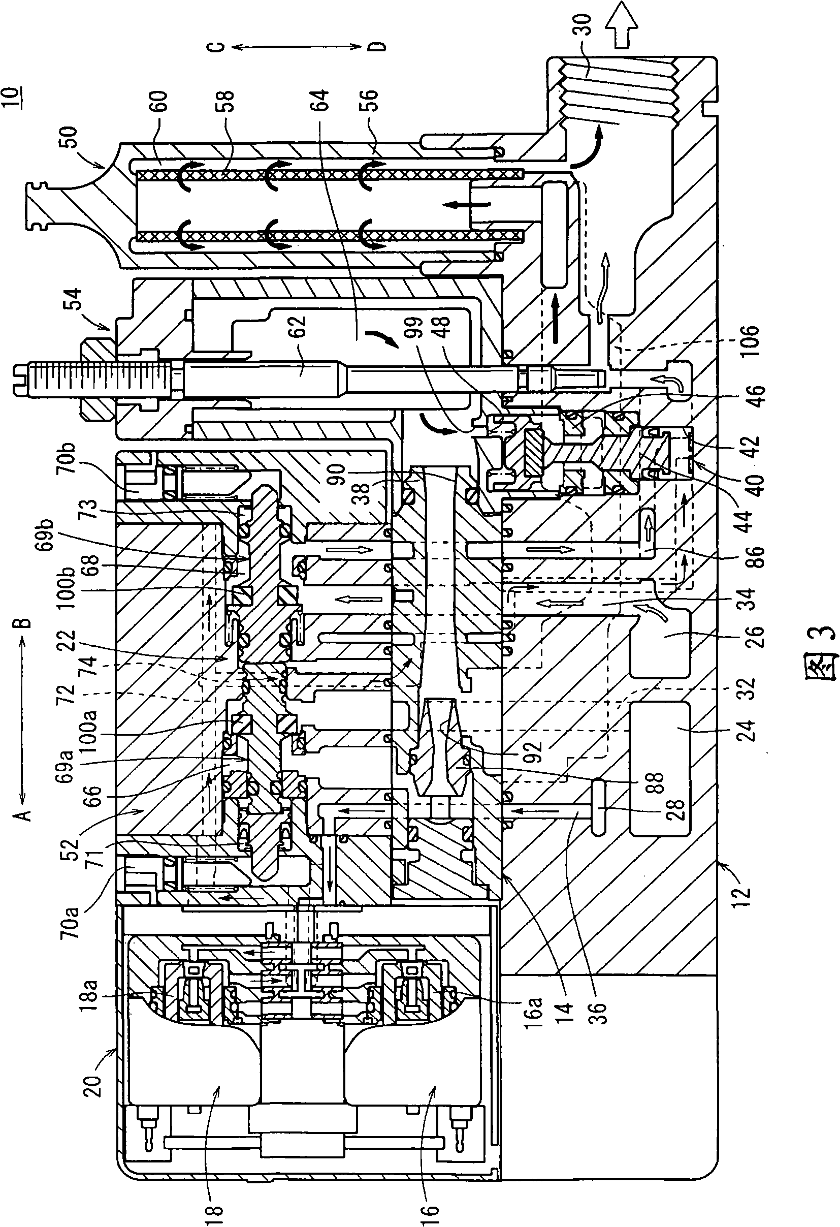
[0020] As shown in FIGS. 1 to 4 , the vacuum generating unit 10 includes a main body 12 formed with a predetermined length; an ejector 14 connected to the top of the main body 12 and serving as a vacuum generating mechanism; disposed at a side of the ejector 14 and having a pilot supply valve 16 and the solenoid valve part 20 of the pilot vacuum disconnect valve 18; arranged on the upper part of the injector 14, moved under the supply of pilot air, for disconnecting the vacuum generating condition that generates negative pressure from the vacuum that releases the negative pressure to the air pressure Switching valve section 22 for switching between conditions.

[0021] The main body 12 has a predetermined length in the longitudinal direction (directions of arrows A and B), wherein on one side of the main body 12, there are provided a supply port 24 for supplying...


PUM


Abstract

The invention discloses a vacuum generating unit. An ejector (14) functioning as a vacuum generating mechanism is disposed in a main body (12) constituting the vacuum generating unit (10), and an atmospheric air introducing valve (40) is disposed between the ejector (14) and a vacuum port (30). The atmospheric air introducing valve (40) is brought into a valve closed state at times when a negative pressure is generated by the ejector (14) under a condition in which a workpiece is held by the negative pressure generated by the ejector, whereby communication between the vacuum port (30) and the atmosphere is blocked. On the other hand, at times when the vacuum is broken, in which the negative pressure state of the vacuum port (30) is released, the atmospheric air introducing valve (40) is brought into a valve open state, whereby the vacuum port (30) communicates with the atmosphere.

Description

technical field [0001] The present invention relates to a vacuum generating unit which supplies negative pressure to a work device such as a suction pad, and more particularly, to a vacuum generating unit having a solenoid valve part inside which can be used between the supply of negative pressure and the negative pressure. Switching between pressure supply cut-offs. Background technique [0002] In general, vacuum generating units are known, which are used, for example, as workpiece transport or positioning means. In such a vacuum generating unit, a suction mechanism such as a suction pad is connected to the unit main body, whereby workpieces can be sucked under suction by means of the suction mechanism under negative pressure supplied from the unit main body. In addition, transportation of the workpiece (the workpiece moves while maintaining the state of suction) is performed, and it is released at a predetermined position by eliminating the state of suction of the workpi...

Claims


Application Information

Patent Timeline
Patent Type & Authority Applications(China)
IPC IPC(8): F04F5/20F04F5/44
CPCF04F5/02F04F3/00Y10T137/86083F16B47/00F15B11/064F15B21/14
Inventor 深野喜弘大岛雅之
Owner SMC CORP
Learn More