Main body and grate running unit of life garbage incinerator

A technology of domestic waste incineration and operation device, applied in incinerators, grate, combustion method and other directions, can solve problems such as affecting the operation of the grate, easy cracking of the furnace, and lack of loosening devices.

Inactive Publication Date: 2002-01-09
江苏三信环保设备有限公司
View PDF2 Cites 4 Cited by
  • Summary
  • Abstract
  • Description
  • Claims
  • Application Information

AI Technical Summary

Problems solved by technology

There are still problems that the garbage is not easy to burn through and the burning time is long
In addition, this patent application also has the following deficiencies: (1) the used furnace plate of the grate of this patent application follows the structure of the front warped furnace plate in 97206929.1, and the used furnace plate is a forward warped furnace plate. The middle part of one side has an upper flanging. Since the furnace plate is in a high temperature environment and is subject to heavy load, the furnace plate of the above structure is easy to deform, mainly because the side without the flange on the furnace plate surface bends downward. Collision with the furnace base partition below it occurs, affecting the operation of the grate
(2) The furnace wall of the furnace body of the patent application is a single layer, which not only has poor thermal insulation performance, but also the furnace is easy to crack during use, causing leakage
Due to the lack of a loosening device, the garbage is easily entangled when feeding, blocking the feeding port
(4) Because the discharge port of the hopper is the feed port of the furnace in this patent application, the discharge port of the hopper is sealed and fixedly connected with the furnace. During use, due to thermal expansion and contraction, the two will crack and leak at the joint. cigarette
(5) The lower beam of the feeding device set on the base of the patent application not only plays a load-bearing role on the furnace together with the base, but also serves as the lower edge of the furnace feed port; when the domestic waste incinerator is in operation, the garbage passes through the hopper It falls to the feed port of the furnace, enters the furnace from the feed port of the furnace under the action of the

Method used


Image

  • Main body and grate running unit of life garbage incinerator
  • Main body and grate running unit of life garbage incinerator
  • Main body and grate running unit of life garbage incinerator

Examples


Embodiment 1

[0062] (Embodiment 1, grate operating device)

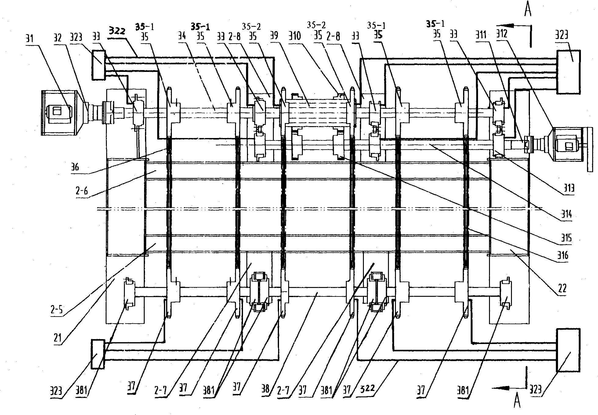
[0063] See figure 1, the grate operating device 3 of the present embodiment has a furnace base 2, six guide rails 316, a main reduction unit 31, a driving shaft 34, a driving shaft bearing, a driving shaft bearing seat 33, an auxiliary reduction unit 312, an auxiliary driving shaft 314, an auxiliary driving Shaft bearing, sub-drive shaft bearing seat 313, sleeve shaft 39, sleeve shaft bearing, driven shaft 38, driven shaft bearing, driven shaft bearing seat 381 and grate components. The driving shaft bearing block 33, the auxiliary driving shaft bearing block 313, the driven shaft bearing block and the guide rail 316 are all fixed on the furnace base 2. The driving shaft bearing is arranged on the driving shaft bearing seat 33, the driving shaft 34 is rotatably connected with the driving shaft bearing seat 33 through the driving shaft bearing, and the driving shaft 34 is connected with the main reduction unit 31. The middle par...

Embodiment 2

[0072] (Embodiment 2, grate operating device)

[0073] The rest are the same as in Embodiment 1, except that the connection between the secondary drive shaft 314 and the sleeve shaft 39 is a chain drive connection; the secondary drive shaft 314 is fixed with 2 active secondary sprockets, and the sleeve shaft 39 is fixed with corresponding 2 sprockets. Each driving secondary sprocket is meshed with a corresponding chain, and each chain is meshed with a corresponding driven secondary sprocket.

Embodiment 3

[0074] (Embodiment 3, the main body of the refuse incinerator)

[0075] See Figure 10 , Furnace base 2 is fixedly connected successively by four furnace base sections of furnace base front section 2-1, first furnace base middle section 2-2, second furnace base middle section 2-3 and furnace base tail section 2-4. Each furnace base section in turn comprises a left box beam 21, a right box beam 22, a cover plate 23, a bottom plate 25, a bracket support beam 28 and a bracket support 28-1. The furnace base front section 2-1 has a rear sealing plate 23, and all the other furnace base sections have two sealing plates 23, which are divided into a front sealing plate and a rear sealing plate. There is a gap for the passage of the fire grate under the sealing plate 23 within the fire grate operating range. The sealing plate 23 and the bottom plate 25 are fixedly connected with the left box beam 21 and the right box beam 22 at the same time. The sealing plate 23 not only plays the r...


PUM


Abstract

A main body and grate unit of life garbage incinerator features that its grate unit is divided into left, central and right subgrates, said left and right subgrates have drive chain wheels fixed to the drive axle for directly driving them, the drive chain wheel of central subgrate is fixed to the sleeve axle arranged in central part of drive axle and is driven by secondary drive axle via gear, chain wheel and chain, and a differentiating movement between left-right subgrates and central subgrate is formed for high combustion speed and full combustion of garbage. Said main body is composed of feeder, base, furnace body, blower and dreg crusher besides said grate unit.

Description

technical field [0001] The invention relates to a main body of a garbage incinerator and a fire grate operating device thereof. Background technique [0002] For domestic waste incineration, such as Chinese patent application 97206929.1, a radiant stepped multi-arch domestic waste incinerator is proposed. More garbage disposal, less smoke and dust emission, higher heat utilization rate. However, when the garbage moves forward with the fire grate, it cannot be turned over on the fire grate, resulting in insufficient combustion, long burn-out time, unstable furnace temperature, and poor heat preservation performance of the furnace. As its improvement, Chinese patent application 99229824.5 has carried out changes on the grate operating mechanism. It constitutes a fire grate, with ventilation holes on the furnace plate, guide rails fixed on the base of the incinerator, and the guide rails are in rolling contact with the chain rollers, and the contact surface between the guide ...

Claims


Application Information

Patent Timeline
IPC IPC(8): F23G5/00F23G5/14F23G5/44F23H11/00
Inventor 葛永琪
Owner 江苏三信环保设备有限公司
Why Eureka
Try Eureka