Hollow mold for filling cast-in-situ concrete

A technology of hollow carcass and cast-in-place concrete, which is applied in the on-site preparation of building components, formwork/formwork/work frame, structural elements, etc., which can solve the problems of building component dislocation, inconvenient layout, and affecting construction efficiency. Achieve the effects of anti-floating positioning, convenient application and operation, and large anchoring force

Inactive Publication Date: 2009-02-11
湖南邱则有专利战略策划有限公司
View PDF3 Cites 0 Cited by
  • Summary
  • Abstract
  • Description
  • Claims
  • Application Information

AI Technical Summary

Problems solved by technology

But when this kind of hollow carcass is applied to the floor construction, the hollow carcass cannot be accurately arranged in the middle layer of the floor, which affects the construction quality of the floor
For this reason, the patent number is ZL01215092.4, and the utility model patent titled "Building Components" discloses a building component that is a polyhedron, which can be hollow or solid. It is arranged in the middle layer of the floor, and the outer wall of the polyhedron is provided with protruding legs, so that when the floor is poured, the legs can ensure that the hollow multi-faceted main cavity is just at the middle layer of the floor. , so as to better solve the above problems, but this kind of building components is inconvenient in the design and construction, and when it is applied to the cast-in-place concrete hollow floor, it is prone to misalignment in the horizontal direction of the building components, which affects the hollow floor. Construction quality, and affect construction efficiency

Method used


Image

  • Hollow mold for filling cast-in-situ concrete
  • Hollow mold for filling cast-in-situ concrete
  • Hollow mold for filling cast-in-situ concrete

Examples


Embodiment Construction

[0080] The present invention will be further described below in conjunction with the accompanying drawings and embodiments.

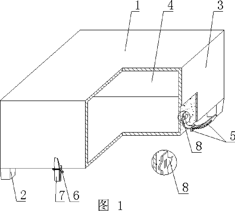
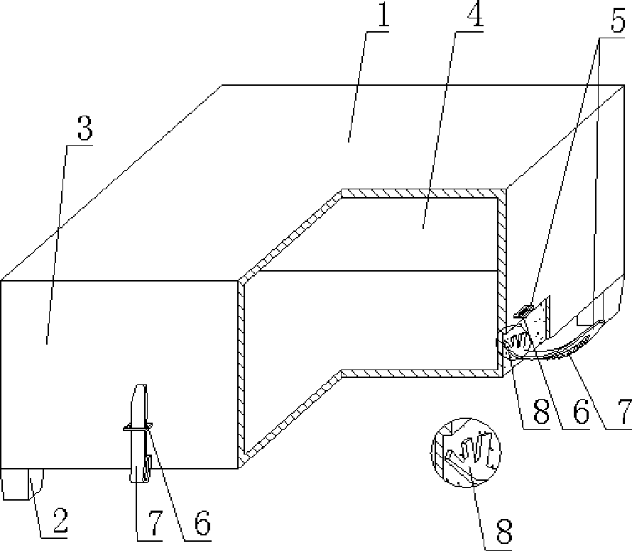
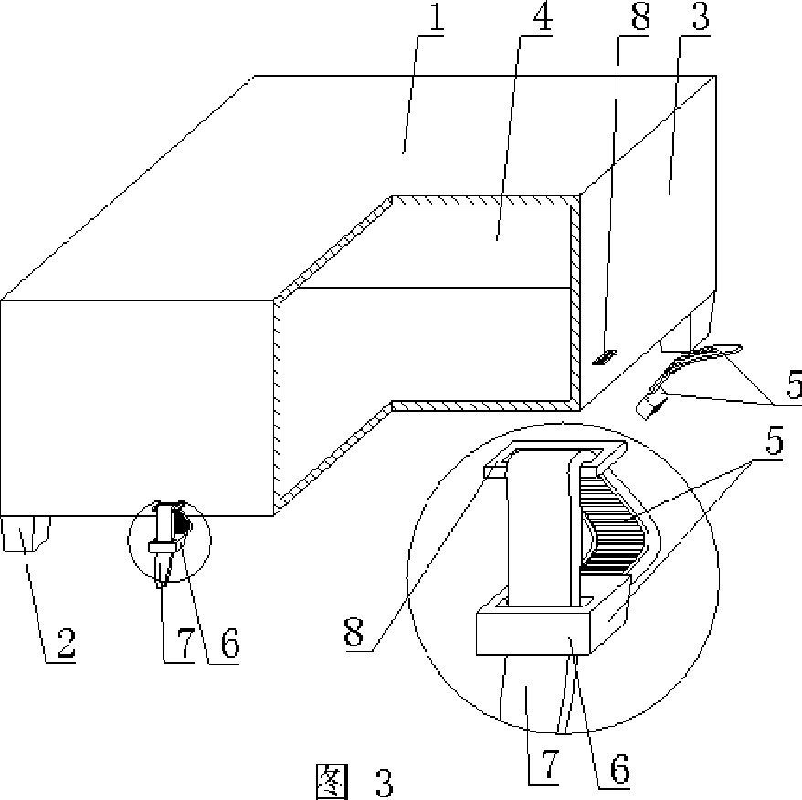
[0081] As shown in the accompanying drawings, the present invention includes a hollow carcass 1 and a support foot 2. The support foot 2 is arranged on the outer wall 3 of the bottom surface of the hollow carcass 1, and the outer wall 3 encloses the hollow carcass 1 with a cavity 4. Its characteristics The hollow carcass 1 or / and the support foot 2 are provided with a locking member 5, the locking member 5 includes a self-locking hole 6 and a self-locking strip or strip 7, and the locking member 5 is supported by an anchor member 8 Anchored in the hollow carcass 1 or the locking member 5 is connected with the anchoring member 8 anchored in the hollow carcass 1, the locking member 5 passes through the support foot 2, and extends the support foot 2 to be exposed, and the support foot 2 is mortar Hard feet, concrete feet or plastic feet. In each accompany...


PUM


Abstract

A hollow matrix for cast-in-situ concrete filling comprises a hollow matrix (1), an arm brace (2) which is arranged on the outer wall (3) on the bottom surface of the hollow matrix (1), and the outer wall (3) forms the hollow matrix (1) with a cavity (4) by enclosing. The hollow matrix is characterized in that the hollow matrix (1) or / and the arm brace (2) is / are provided with a locking element (5) which comprises a self-locking hole (6) and a self-locking strip or band (7), the locking element (5) is anchored in the hollow matrix (1) by an anchoring element (8), or the locking element (5) is connected with the anchoring element (8) which is anchored in the hollow matrix (1), the locking element (5) penetrates and extends out the arm brace (2), and the arm brace (2) is made of a mortar hard brace, or a concrete brace, or a plastic brace. The hollow matrix is applicable to cast-in-situ reinforced concrete or prestressed reinforced concrete hollow slabs, floors, roofs, walls, foundation slabs and bridges, especially to hollow flat slabs.

Description

[0001] This application is a divisional application of an invention patent application with an application date of August 26, 2004, an application number of 200410155256.6, and a title of "a hollow matrix for filling cast-in-place concrete". (1) Technical field [0002] The invention relates to a hollow matrix for filling cast-in-place concrete. (2) Background technology [0003] At present, the cast-in-place concrete hollow floor is a widely used floor structure. The lightweight permanent tire molds filled in it include various hollow tubes and boxes, and the boxes are hollow or solid. For example, the patent No. ZL99249798.1, which the applicant applied for on November 29, 1999, is a utility model patent named "fiber-reinforced thin-walled member for reinforced concrete filling", which discloses a thin-walled formwork member, including an upper plate, The surrounding side walls, the lower bottom, and the upper plate, the surrounding side walls and the lower bottom form a p...

Claims


Application Information

Patent Timeline
Patent Type & Authority Applications(China)
IPC IPC(8): E04G15/06E04B5/36E04B5/48E04C5/00E04C5/16
Inventor 邱则有
Owner 湖南邱则有专利战略策划有限公司
Why Eureka
Try Eureka