
Expansion anchor rod

A technology of expanding bolts and bolts, which is applied in the installation of bolts, construction, excavation, etc., can solve the problem of soft rock and large deformation roadway support, and the limitation of the strength and creep resistance of the bolt body , single anchoring force of the anchor rod, etc., to achieve the effect of wide selection of structures and materials, wide range of structures and materials, and large anchoring force

Inactive Publication Date: 2008-02-20
SHANDONG UNIV
View PDF3 Cites 14 Cited by
  • Summary
  • Abstract
  • Description
  • Claims
  • Application Information

AI Technical Summary

Problems solved by technology

The materials used for full-length anchor bolts are all rigid materials, which are filled and bonded with the anchored rock formations through various adhesives. This type of anchor bolts mainly has the following disadvantages: 1. The construction and installation are complicated and the construction period is short. 2. It cannot compensate the anchor hole change caused by the movement of the rock formation, especially it cannot solve the support problem of soft rock and large deformation roadway well; 3. The anchor rod is not easy to recover
There are the following disadvantages in anchoring the anchor rod at the end: 1. The anchoring force of the anchor rod is single. Once the expansion force is not enough, it will slip off, which will easily cause the anchor rod to fail; 2. The anchor rod cannot be recovered.
However, due to the limitations of the existing "flexible injection anchor" material and structure, the improvement of the strength and creep resistance of the anchor body is limited.

Method used


Image

  • Expansion anchor rod
  • Expansion anchor rod
  • Expansion anchor rod

Examples


Embodiment approach 1

[0024] 1. Embodiment 1: Anchors with circular cross-sections and expansion bolts

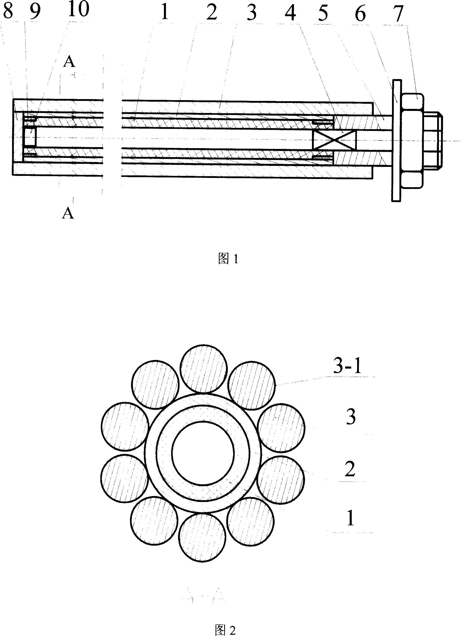
[0025] Coal mines usually use a drill bit with a diameter of 28mm to drill the anchor hole to place the anchor rod. In order to facilitate the installation of the "expansion anchor rod", the diameter of the anchor rod body is slightly smaller than the diameter of the drill bit, which is determined to be 27mm, and the length of the anchor rod is 2 meters. As shown in Figure 1 and Figure 2, the expansion body 1 is a straight cylindrical rubber bladder made of rubber with an outer diameter of 15mm and a thickness of 2mm; the expansion force transmission layer 2 is a circumferential fracture rolled with a 0.3mm thin metal plate, And overlap the cylinder for a week; the circular cross-section anchor 3-1 of the anchor layer 3 is a round steel bar or round threaded steel bar with a diameter of 5mm; the injection valve 4 is a valve core for an aviation tire; the pipe hole anchor head 5 is a Threaded ste...

Embodiment approach 2

[0028] 2. Embodiment 2: Anchors with rectangular cross-section expand the anchor rod

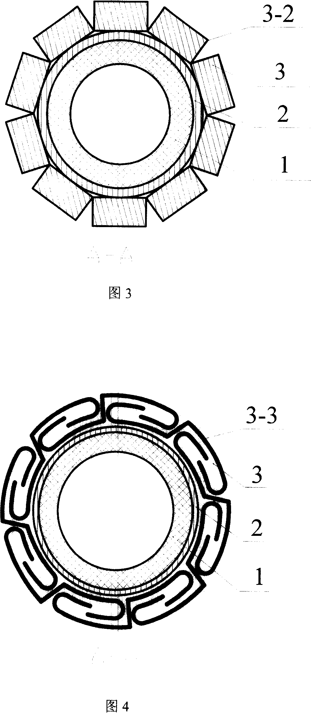
[0029] As shown in Figure 3, a rectangular anchor 3-2 with a cross-sectional size of 8×5 mm is selected to form an expansion anchor rod, and the others are the same as in the first embodiment.

[0030] Compared with Embodiment 1, the difference of this structure is only on the anchoring layer 3, the circular anchoring piece is replaced by the rectangular anchoring piece, which greatly increases the contact area between the anchoring layer 3 and the surrounding rock mass, and improves the anchoring force. According to the different grades of steel used in the anchor, the anchor rod can provide a maximum anchoring force of 120-340kN.

Embodiment approach 3

[0031] 3. Implementation plan three: S-shaped cross-section anchor expansion anchor rod

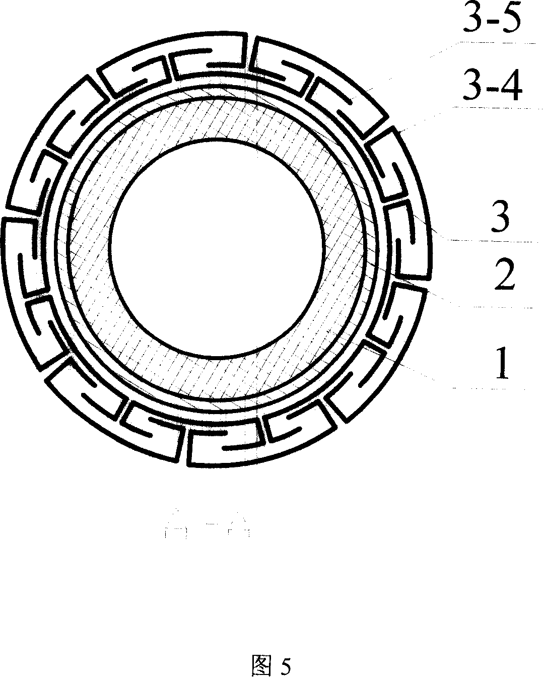
[0032]As shown in Figure 4, the expansion force transmission layer 2 is a circular closed cylinder braided with high-strength and high-elastic fibers, which is set on the expansion body; steel strips with a thickness of 1.5 mm are used to make S-shaped anchors 3-3 The anchoring layers are interlocked and linked one by one to form a circularly stretchable cylindrical structure, and are fitted on the outer edge of the expansion force transmission layer to form an expansion anchor rod, and the others are the same as in the first embodiment.

[0033] Compared with Embodiment 1, the difference of this structure is that the anchoring layer 3 is replaced by a circular anchoring piece by an S-shaped anchoring piece, which increases the contact area between the anchoring layer 3 and the surrounding rock mass and improves the anchoring force. At the same time, the anchoring layer 3 It has the abili...


PUM

PropertyMeasurementUnit
diameteraaaaaaaaaa
thicknessaaaaaaaaaa
thicknessaaaaaaaaaa

Abstract

The invention relates to the technical field of a support facility for the rock, earth and mining engineering, in particular to an expansion anchor rod. The expansion material of the anchor rod adopts a high-elasticity high molecular material, or a compound intensified material made of the steel wire or fibrous material and the high-elasticity and high molecular material or the thin corrugated metal sheet. The expansion body of the anchor rod has a hollow structure; the hollow part is a pressure cavity for injection, one end of the cavity is sealed and an introduction valve and a tube orifice anchor head are closely arranged at the other end ; an expansive force transfer layer is sleeved around the outer edge of the expansion body of the anchor rod and an anchor layer is sleeved around the outer edge of the expansive force transfer layer to form the expansion anchor rod. The expansion anchor rod additionally has the advantages of the rigid anchor rod on the base of keeping the application effect of the flexible injection bolt. The anchoring force is reliable and is easy to be adjusted, supplement and reclaimed; the creep resistance is strong and the anchoring effect is not affected if the geotechnical or the hole wall has honeycombed crack or collapse of artifices; also, the anchor rod is high in strength, low in cost, wear-resistant and is easy to be processed and manufactured.

Description

1. Technical field [0001] The invention relates to the technical field of geotechnical and mine engineering support facilities, in particular to an expansion bolt. 2. Background technology [0002] In the mining process of geotechnical, tunnel and coal mines, bolt support is a surrounding rock control technology with two functions of support and reinforcement. Compared with frame support, the use of bolt support technology has significant economic benefits. [0003] Traditional bolts can be divided into full-length anchor bolts and end anchor bolts. The materials used for full-length anchor bolts are all rigid materials, which are filled and bonded with the anchored rock formations through various adhesives. This type of anchor bolts mainly has the following disadvantages: 1. The construction and installation are complicated and the construction period is short. 2. It cannot compensate the change of the anchor hole caused by the movement of the rock formation, especially th...

Claims


Application Information

Patent Timeline
Patent Type & Authority Applications(China)
IPC IPC(8): E21D21/00E02D17/20
Inventor 王威强颜建成陈中合
Owner SHANDONG UNIV
Learn More