Active anchoring mechanism with two-time drive function

An active and anchoring technology, applied in infrastructure engineering, construction, sheet pile walls, etc., can solve the problems of non-deformable anchor tip and small anchoring force, and achieve the effect of low cost, high anchoring force and improving anchoring force.

Active Publication Date: 2013-06-26
HARBIN INST OF TECH
View PDF5 Cites 14 Cited by
  • Summary
  • Abstract
  • Description
  • Claims
  • Application Information

AI Technical Summary

Problems solved by technology

[0023] The present invention aims to solve the problem that the anchor tip cannot be deformed in the existing anchoring mechanism, so that the anchoring force is small after the medium is penetrated, and further provides an active anchoring mechanism with a secondary driving function

Method used


Image

  • Active anchoring mechanism with two-time drive function
  • Active anchoring mechanism with two-time drive function

Examples


specific Embodiment approach 1

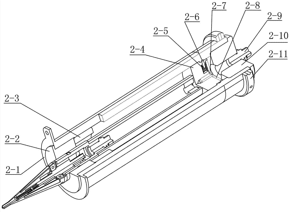
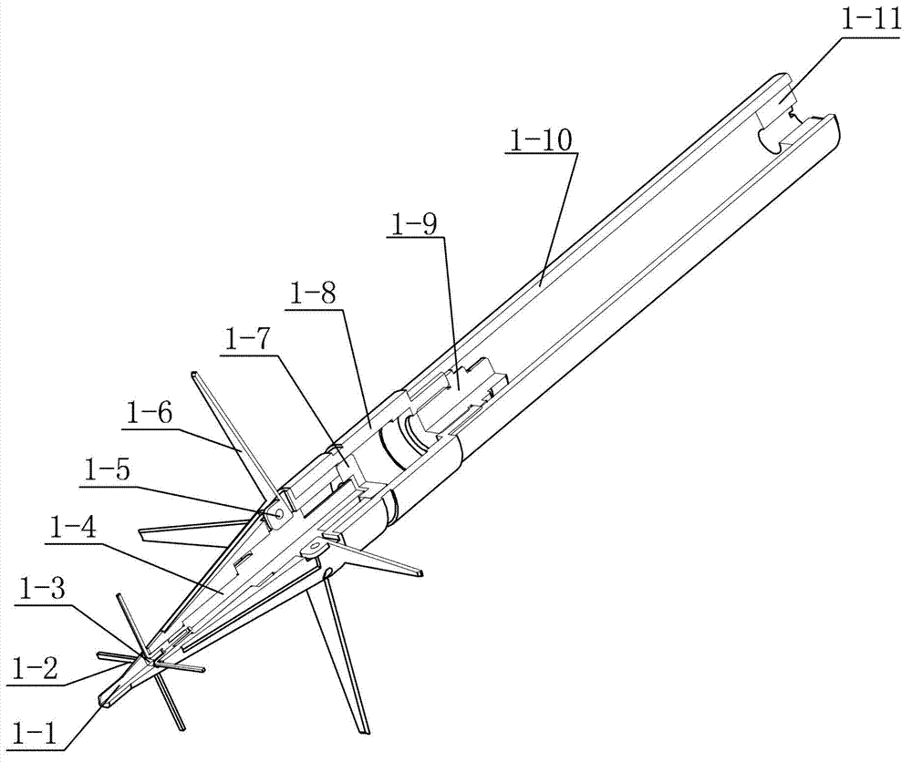
[0033] Specific implementation mode one: as Figure 1~2 As shown, the active anchoring mechanism with a secondary driving function in this embodiment is composed of an anchoring unit 1 and a propulsion unit 2;

[0034] The anchor unit 1 includes an anchor tip 1-1, an anchor claw 1-2, an inverted cone 1-3, a stepped push rod 1-4, a piston 1-7, a combustion chamber 1-8, an pyrotechnic device 1-9, an anchor A rod 1-10, an anchor rod end cover 1-11, a plurality of evenly distributed spreading wing pins 1-5 and a plurality of uniformly spreading spreading wings 1-6; the anchor tip 1-1, the combustion chamber 1-8 and the anchor rod 1-10 are all hollow structures, one end of the anchor tip 1-1 is larger and the other end is smaller, the larger end of the anchor tip 1-1 is threadedly connected to one end of the combustion chamber 1-8, and the other end of the combustion chamber 1-8 is connected to the anchor rod 1 One end of -10 is threaded, the other end of the combustion chamber 1-...

specific Embodiment approach 2

[0039] Specific implementation mode two: as figure 1 and figure 2 As shown, the small end of the anchor tip 1-1 in this embodiment is conical, and the large end of the anchor tip 1-1 is cylindrical. Such setting can increase the penetration depth and increase the anchoring force. Other compositions and connection methods are the same as those in Embodiment 1.

specific Embodiment approach 3

[0040] Specific implementation mode three: as figure 1 and figure 2 As shown, the number of piston rods 2-6 in this embodiment is two to six. With such a setting, the exit speed of the anchor body can be adjusted to achieve different penetration speeds. Other compositions and connection methods are the same as those in Embodiment 1 or 2.


PUM


Abstract

The invention provides an active anchoring mechanism with the two-time drive function and relates to the active anchoring mechanism. The active anchoring mechanism aims at solving the problem that anchoring force is small after media are thrown into an existing anchoring mechanism due to the fact that an anchor tip in the existing anchoring mechanism can not be deformed. The large end of a step pushing rod is fixedly connected with a piston. A back taper is arranged inside the anchor tip and is arranged adjacent to the small end of the step pushing rod. An anchoring claw is fixed at the small end of the step pushing rod. Each stretching wing is installed on the large end of the anchor tip through each stretching wing pin, and a plurality of the stretching wings are arranged in a star-shaped mode. A thrust end cover is connected with the lower end of an expansion cylinder in a threaded mode. An anti-vibration pad is arranged on the upper end face of the thrust end cover. A piston body is arranged inside the expansion cylinder and connected with the expansion cylinder in a sliding mode. A plurality of blind holes are evenly distributed in the piston body along the radial direction of the piston body. A fire device is arranged on a fire connector. The outer wall of the upper end of the expansion cylinder is connected with a limiting ring in a threaded mode. The outer wall of a combustion room of an anchoring unit is in sliding connection with the inner wall of an end cover of the expansion cylinder. The active anchoring mechanism is applied to anchoring of landing devices and instruments and equipment under a micro gravity environment.

Description

technical field [0001] The invention relates to an anchoring mechanism for anchoring instruments and equipment in a microgravity environment, and belongs to the technical field of deep space detection and positioning systems. Background technique [0002] Microgravity is mainly reflected in deep space exploration. The development of space technology has made it possible for humans to launch probes to certain planets in the solar system, land on the surface of some planets to retrieve soil and rock samples, and understand and use planets through scientific experiments. So far, humans have landed on the surface of the moon and Mars, and successfully retrieved lunar soil and rock samples. In addition to the moon and Mars, humans have also launched landers to Venus, Jupiter, asteroids, and comets. With the advent of the 21st century, deep space exploration technology, as an important means for human beings to protect the earth, enter the universe and find new living homes, has ...

Claims


Application Information

Patent Timeline
Patent Type & Authority Applications(China)
IPC IPC(8): E02D5/80
Inventor 赵志军赵京东王爽刘宏
Owner HARBIN INST OF TECH
Why Eureka
Try Eureka