Centrifugal ball type braking device for vertical shaft type windmill

A braking device, vertical shaft technology, applied in wind turbines, control of wind turbines, wind turbines at right angles to the wind direction, etc. The effect of easy operation, cost saving and efficiency improvement

Inactive Publication Date: 2009-02-11
北京九艺通文化艺术有限公司
View PDF0 Cites 9 Cited by
  • Summary
  • Abstract
  • Description
  • Claims
  • Application Information

AI Technical Summary

Problems solved by technology

When the wind speed exceeds 8M / S, its torque and speed will increase. At this time, its output power will be greater than 1000W and cause the generator to be burned. The current solution is to shut down and stop the generator. When the wind speed is insufficient or exceeds the rated wind speed, the generator It cannot be used normally, which not only wastes resources, but also has a low utilization rate of wind turbines, so although this vertical shaft wind turbine has a simple structure, it is not conducive to wide application

Method used


Image

  • Centrifugal ball type braking device for vertical shaft type windmill
  • Centrifugal ball type braking device for vertical shaft type windmill
  • Centrifugal ball type braking device for vertical shaft type windmill

Examples


Embodiment 1

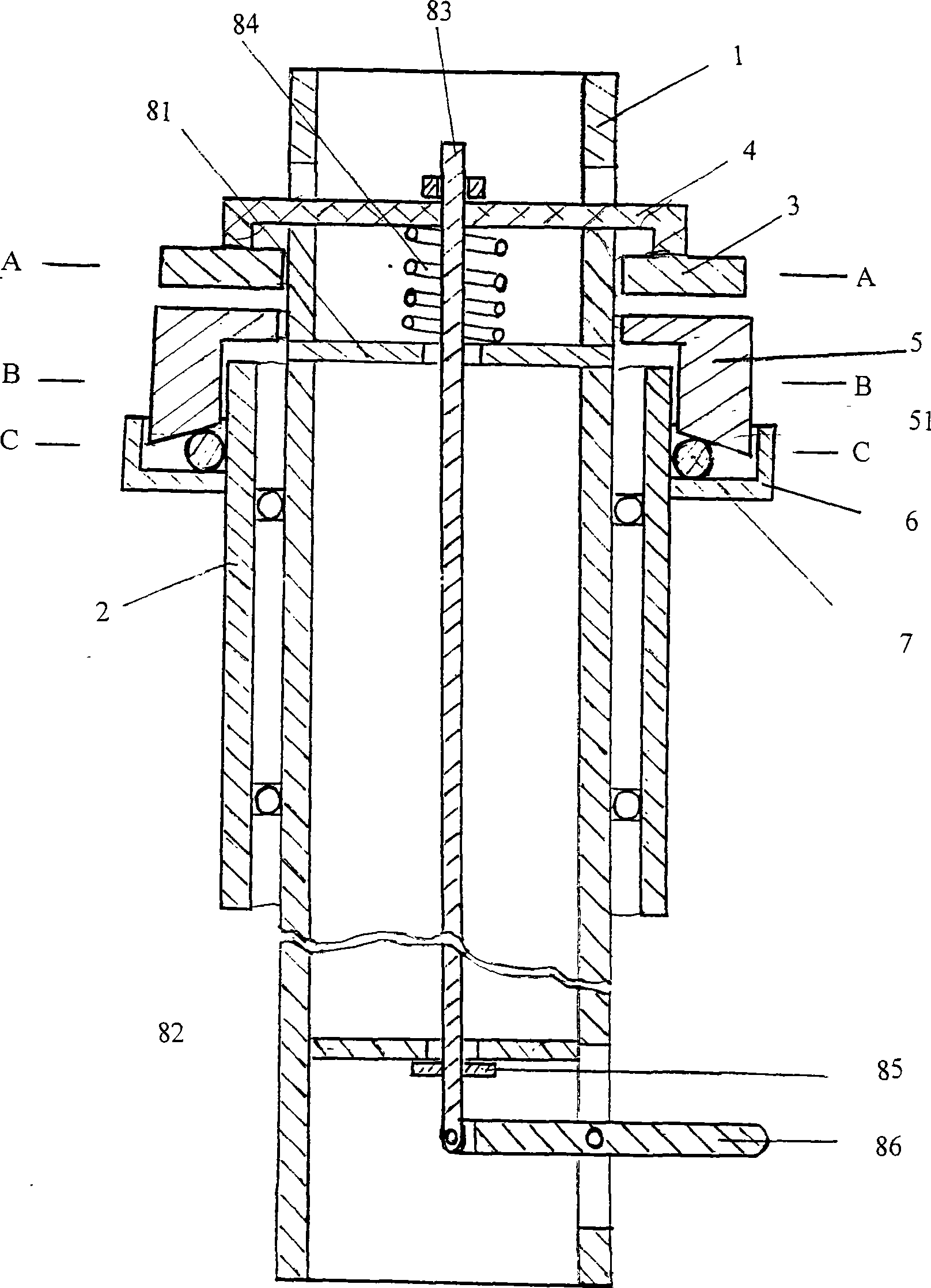
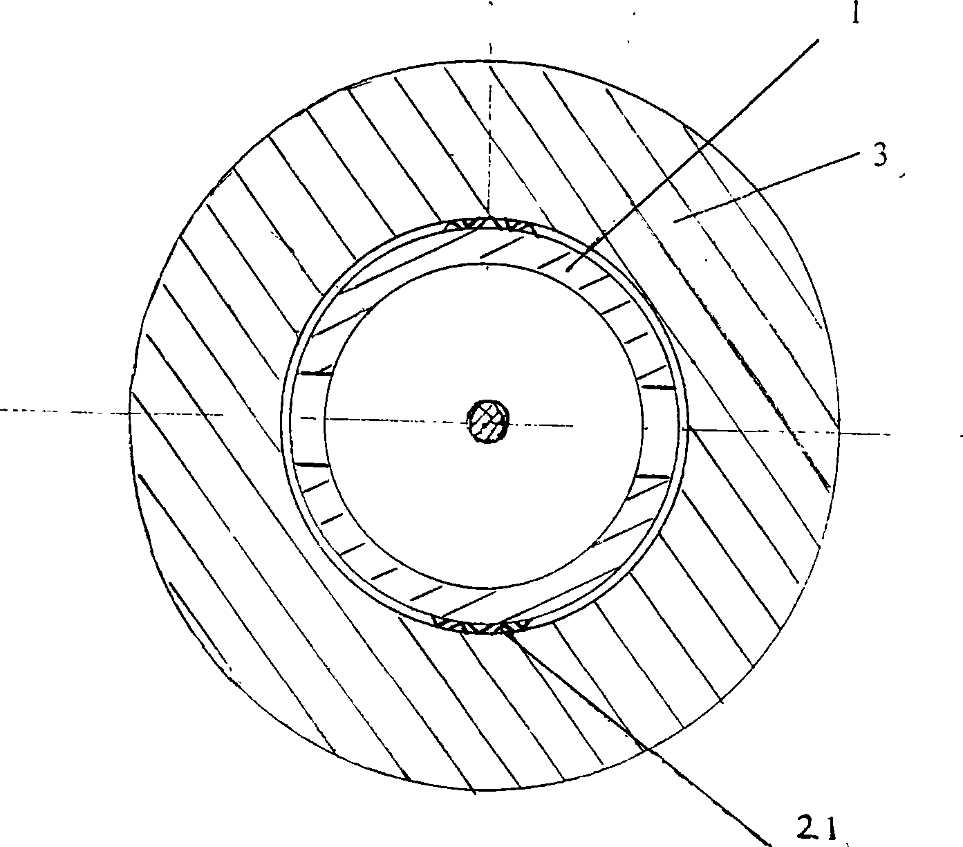
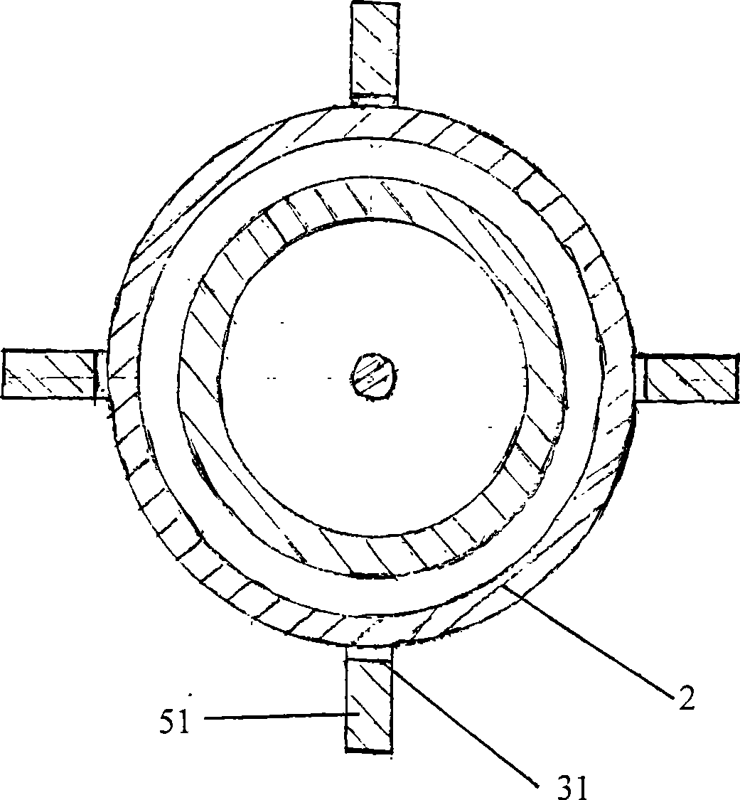
[0018] The structure of the centrifugal ball braking device of the wind power generator in this embodiment is as follows: figure 1 As shown, the device includes a hollow inner shaft 1, a shaft sleeve 2, an upper brake disc 3, a connecting rod 4, a lower brake disc 5, a centrifugal ball rolling groove 5, and a centrifugal ball 6; the shaft sleeve 2 is set on the hollow inner shaft 1, the shaft sleeve 2 and the hollow inner shaft 1 are connected by bearings; the longitudinal section of the upper brake disc 3 with a central through hole is flat and rectangular, and the upper brake disc 3 is set outside the hollow inner shaft 1 , the inner side wall of the upper brake disc 3 and the outer wall of the hollow inner shaft 1 are connected by a key; The shaft 1 has a through hole, and the lower end surface of the longitudinal rod is fixedly connected with the upper bottom surface of the upper brake disc 3; It is composed of at least two legs 51 that are distributed symmetrically and e...

Embodiment 2

[0024] The structure of the wind power generator centrifugal ball type hand brake device of this embodiment is as follows: figure 1 As shown, the hand brake is placed in the hollow inner shaft 1, and the hand brake includes upper and lower positioning supports 81, 82, a transmission connecting rod 83, a return spring 84, a limit ring 85, and a brake handle 86; the upper and lower positioning supports 81, 82 are respectively fixed on the upper and lower ends of the hollow inner shaft 1. There are holes in the center of the upper and lower positioning supports 81, 82. The transmission connecting rod 83 passes through the holes in the centers of the upper and lower positioning supports 81, 82. The transmission connecting rod 83 The upper end is fixed on the connecting rod 4 of the upper brake disc 3, the lower end of the transmission connecting rod 83 is fixed with a limit ring 85, and the limit ring 85 is pushed against the lower positioning support 82. The connection of the uppe...


PUM


Abstract

The invention relates to a vertical shaft typed windmill centrifugal ball typed braking device, belonging to the technical field of wind power generation. The device comprises a hollow inner shaft, a shaft sheath, an upper braking disc, a connection rod, a lower braking disc, a centrifugal ball rolling groove, a centrifugal ball, and a hand brake. The hand brake comprises a transmission connection rod, a connection rod location support, a returning spring, a limit ring and a brake handle. When wind speed exceeds a rated wind speed, centrifugal force increases and the centrifugal ball rolls outwards, propping up the support leg of the lower braking disc and pushing the lower braking disc upwards to contact the upper braking disc, thus starting the brake. Due to the brake, the rev deceases, and the centrifugal force reduces and the centrifugal ball rolls inwards, leading the support leg of the lower braking disc to fall back and the lower braking disc to descend, thus canceling the brake. Then a process of 'brake-speed reducing-speed increasing-brake' is formed. By reducing the rev of the generator to the rated rev and assuring the generator of normal work with an improved efficiency, the vertical shaft typed windmill centrifugal ball typed braking device combines the hand brake with an auto brake and has the advantages of simple structure, convenient operation and cost saving.

Description

technical field [0001] The invention belongs to the technical field of wind power generation, in particular to the structural design of a vertical shaft windmill braking device. Background technique [0002] There are two types of wind turbines: vertical axis wind turbines and horizontal axis wind turbines. Horizontal axis wind turbines are generally used in the world, because horizontal axis power generation equipment can change the windward angle of the blades through electronic control to adjust the torque and speed. , so that it maintains a relatively stable output power, while the vertical axis wind power generation equipment cannot change the windward angle of the blades when the wind speed changes, so it cannot adjust the torque and speed, and cannot maintain a relatively stable output power. This is also the vertical axis and horizontal axis. One of the main differences in wind turbines, [0003] For example, a vertical shaft wind turbine has a rated power of 1000W,...

Claims


Application Information

Patent Timeline
Patent Type & Authority Applications(China)
IPC IPC(8): F03D3/00F03D7/06F03D11/00
CPCY02E10/74
Inventor 夏靖友
Owner 北京九艺通文化艺术有限公司
Why Eureka
Try Eureka