

LCD device, backlight module thereof and display method
A technology of a backlight module and a display method, which is applied in the directions of optics, nonlinear optics, static indicators, etc., and can solve problems such as reducing the contrast of the screen
- Summary
- Abstract
- Description
- Claims
- Application Information
AI Technical Summary
Problems solved by technology
Method used
Image

Examples
no. 1 example
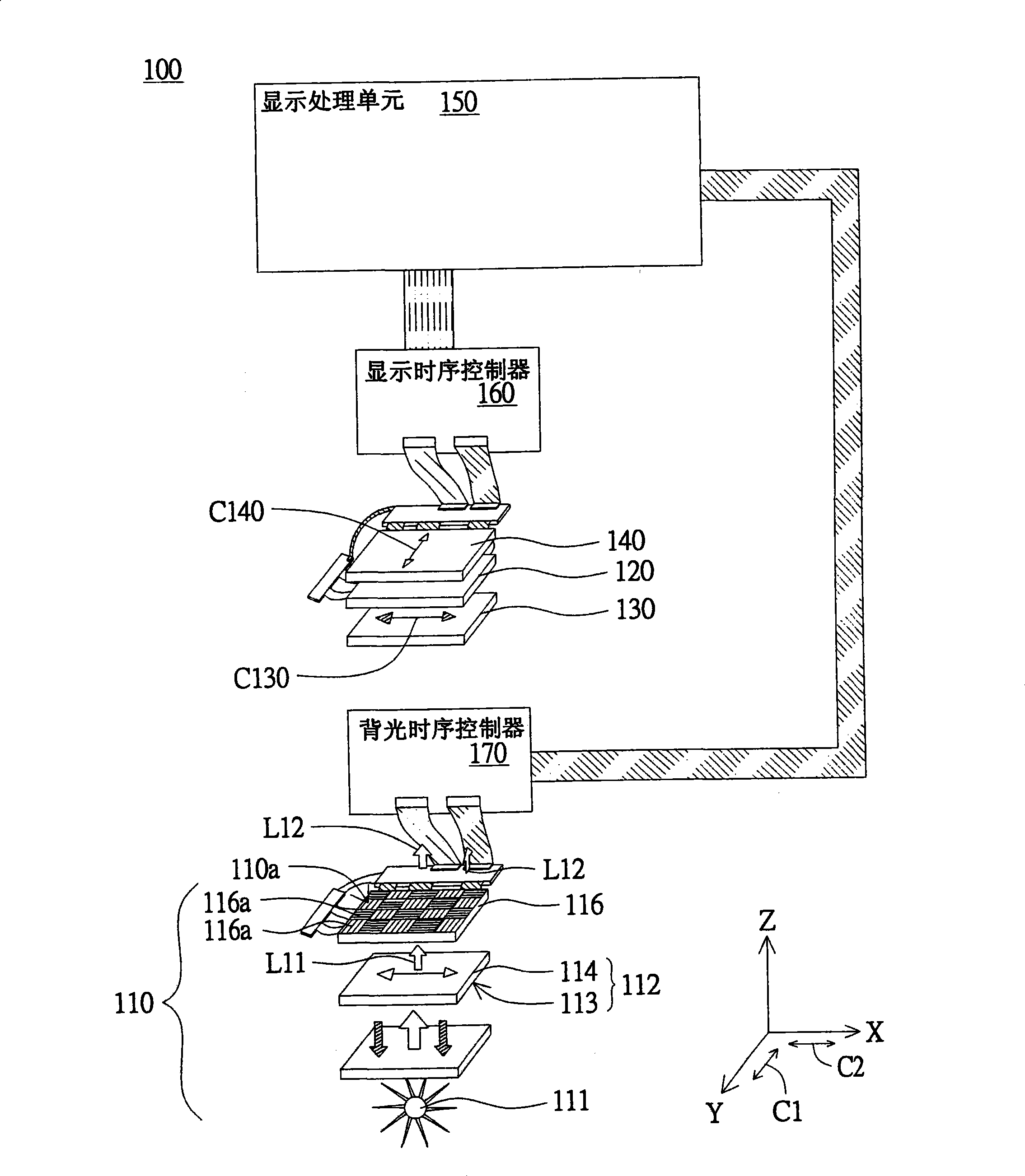
[0081] Please refer to image 3 , Which shows a schematic diagram of the liquid crystal display device 100 according to the first embodiment of the present invention. The liquid crystal display device 100 includes a backlight module 110, a display panel 120, a first polarizing plate 130 and a second polarizing plate 140. The backlight module 110 has a light emitting surface 110a. The backlight module 110 includes a light emitting component 111, a polarizing component 112 and a modulation component 116. The light emitting component 111 is used to provide a light source. After the light source passes through the polarizing component 112, the first polarized light L11 is formed. The modulation component 116 has a plurality of modulation regions 116a. Each modulation area 116a corresponds to a modulation direction C1 or C2. After the first polarized light L11 passes through the modulation regions 116a, a plurality of second polarized lights L12 are formed and emitted from the light em...
no. 2 example
[0096] The difference between the liquid crystal display device 200 of this embodiment and the liquid crystal display device 100 of the first embodiment lies in the polarizing component 212 of the backlight module 210, and the remaining similarities are not repeated here. Please refer to Picture 9 , Which shows a schematic diagram of the liquid crystal display device 200 of the second embodiment. In this embodiment, the first polarized light L11 is linearly polarized, and the modulating component 116 corresponds to a 1 / 2 wavelength phase difference. The polarizing component 212 includes a circular polarizing plate 215 and a linear modulating plate 214. Among them, the circular polarizing plate 215 has a brightness enhancement film 213.
[0097] After the light source passes through the circular polarizing plate 215, the light source forms the first polarized light L11 in a circular polarization state. At the same time, the brightness enhancement film 213 can reflect the light sou...
no. 3 example
[0101] The difference between the liquid crystal display device 300 of this embodiment and the liquid crystal display device 100 of the first embodiment lies in the modulation component 316 and the polarizing component 312 of the backlight module 310, and the rest of the similarities will not be repeated. Please refer to Picture 10 , Which shows a schematic diagram of the liquid crystal display device 300 of the third embodiment. In this embodiment, the first polarized light L31 is in a circular polarization state, and the modulation component 316 corresponds to a phase difference of 1 / 4 wavelength or 3 / 4 wavelength. The polarizing component 312 includes a circular polarizing plate 315. The circular polarizing plate 315 has a brightness enhancement film 313.
[0102] When the light source passes through the circular polarizing plate 315, the light source forms the first polarized light L31 in the circular polarization state 315. At the same time, the brightness enhancement film 31...
PUM
 Abstract
Description
Claims
Application Information