Sensing circuit and method for phase-change memory

A technology of phase-change memory and sensing circuit, which is applied in the direction of static memory, digital memory information, information storage, etc., and can solve the problem of slow reading speed

Inactive Publication Date: 2009-02-11
IND TECH RES INST
View PDF1 Cites 20 Cited by
  • Summary
  • Abstract
  • Description
  • Claims
  • Application Information

AI Technical Summary

Problems solved by technology

[0002] figure 1 It is a sensing circuit diagram of a traditional phase-change memory, in figure 1 In, a current I R Flowing through a phase-change memory unit 115, since the resistance value of the phase-change memory unit 115 varies with its storage state, the current I R The voltage drop generated at both ends of the phase-change memory unit 115 is also different, and the voltage is sent to a comparator 130 and compared with a reference voltage V REF By comparison, the storage state of the phase-change memory unit 115 can be judged. Generally speaking, the comparator 130 is an analog circuit, which can distinguish subtle differences through design. However, due to the resistance and capacitance load on the bit line Delays the charging time to convert current to voltage, so the reading speed is slower

Method used


Image

  • Sensing circuit and method for phase-change memory
  • Sensing circuit and method for phase-change memory
  • Sensing circuit and method for phase-change memory

Examples


Embodiment Construction

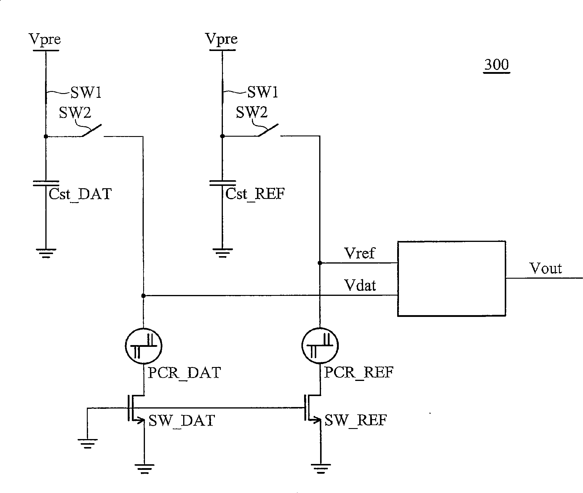
[0033] Figure 3A and 3B Shown is a sensing circuit of a phase change memory according to an embodiment of the present invention. The sensing circuit 300 includes a storage capacitor Cst_DAT and a reference capacitor Cst_REF, a storage storage element PCR_DAT and a reference storage element PCR_REF, and a storage discharge switch. SW_DAT, a reference discharge switch SW_REF and a judging device 310, the first end of the storage capacitor Cst_DAT and the reference capacitor Cst_REF are respectively coupled to a precharge voltage Vpre through a first switch SW1, and the second end is coupled to The ground end, the first ends of the storage storage element PCR_DAT and the reference storage element PCR_REF are respectively coupled to the first ends of the storage capacitor Cst_DAT and the reference capacitor Cst_REF through a second switch SW2, more specifically, the storage The storage element PCR_DAT and the reference storage element PCR_REF are both phase-change memory cells. ...


PUM


Abstract

A sensing circuit for a phase change memory comprises a first storage capacitor and a reference capacitor, a storage memory element and a reference memory element, a storage discharge switch and a reference discharge switch, and a judgment device. The first ends of the storage capacitor and the reference capacitor are both coupled with a pre-charged voltage via a first switch, the first ends of the storage memory element and the reference memory element are respectively coupled with the first ends of the storage capacitor and the reference capacitor via a second switch, the storage discharge switch and the reference discharge switch are respectively coupled with the first ends of the storage memory element and the reference memory element, and the judgment device is coupled with the first ends of the storage memory element and the reference memory element and provides an output as the read result of the storage state of the storage memory element.

Description

technical field [0001] The invention relates to a phase-change memory, in particular to a sensing / reading circuit of the phase-change memory. Background technique [0002] figure 1 It is a sensing circuit diagram of a traditional phase-change memory, in figure 1 In, a current I R Flowing through a phase-change memory unit 115, since the resistance value of the phase-change memory unit 115 varies with its storage state, the current I R The voltage drop generated at both ends of the phase-change memory unit 115 is also different, and the voltage is sent to a comparator 130 and compared with a reference voltage V REF By comparison, the storage state of the phase-change memory unit 115 can be judged. Generally speaking, the comparator 130 is an analog circuit, which can distinguish subtle differences through design. However, due to the resistance and capacitance load on the bit line It delays the charging time to convert the current to voltage, so the reading speed is slower...

Claims


Application Information

Patent Timeline
Patent Type & Authority Applications(China)
IPC IPC(8): G11C7/06G11C11/56
Inventor 林烈萩许世玄江培嘉
Owner IND TECH RES INST
Why Eureka
Try Eureka