
Apparatus and method for governing display lightness of automobile instrument

A technology for displaying brightness and automotive instrumentation, which is applied in the direction of vehicle interior lighting devices, signal devices, instruments, etc., which can solve problems such as roughness, violation of the purpose of energy saving, and inconvenience for drivers to obtain information, so as to achieve energy saving and convenient use.

Active Publication Date: 2009-02-18
BYD CO LTD
View PDF1 Cites 16 Cited by
  • Summary
  • Abstract
  • Description
  • Claims
  • Application Information

AI Technical Summary

Problems solved by technology

[0003] However, the display brightness of the existing instrument panel is generally fixed when the car leaves the factory, or it can only be manually adjusted in a few gears. The brightness is adjusted to the best state to meet different visual needs, and it is inconvenient for drivers to obtain information

Method used


Image

  • Apparatus and method for governing display lightness of automobile instrument
  • Apparatus and method for governing display lightness of automobile instrument
  • Apparatus and method for governing display lightness of automobile instrument

Examples


Embodiment 1

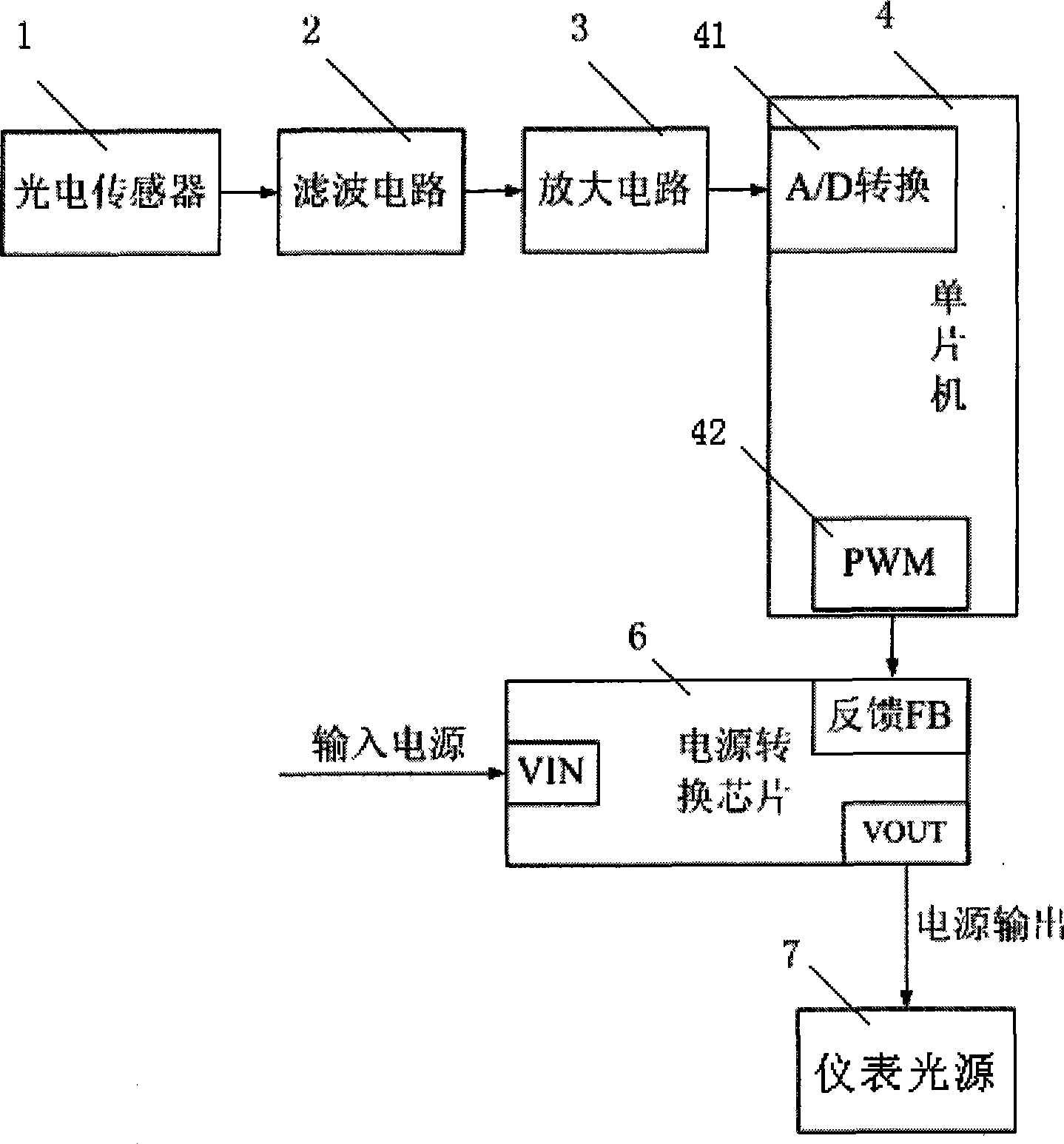
[0042] see figure 1 , the automotive instrument display brightness adjustment device in this embodiment includes a photoelectric sensor 1 , a filter circuit 2 , an amplifier circuit 3 , a processor and a power conversion module 6 . Wherein the processor adopts single-chip microcomputer 4. The single chip microcomputer 4 uses its internal A / D conversion circuit 41 and pulse width modulator 42 . The output end of the photoelectric sensor 1 is connected to the input end of the filter circuit 2, the output end of the filter circuit 2 is connected to the input end of the amplifier circuit 3, the output end of the amplifier circuit 3 is connected to the A / D input port of the single-chip microcomputer 4, and the pulse width modulation of the single-chip microcomputer 4 The converter output port is connected to the feedback input terminal FB of the power conversion module 6 . The power output terminal VOUT of the power conversion module 6 is coupled to the indicating instrument 7 . ...

Embodiment 2

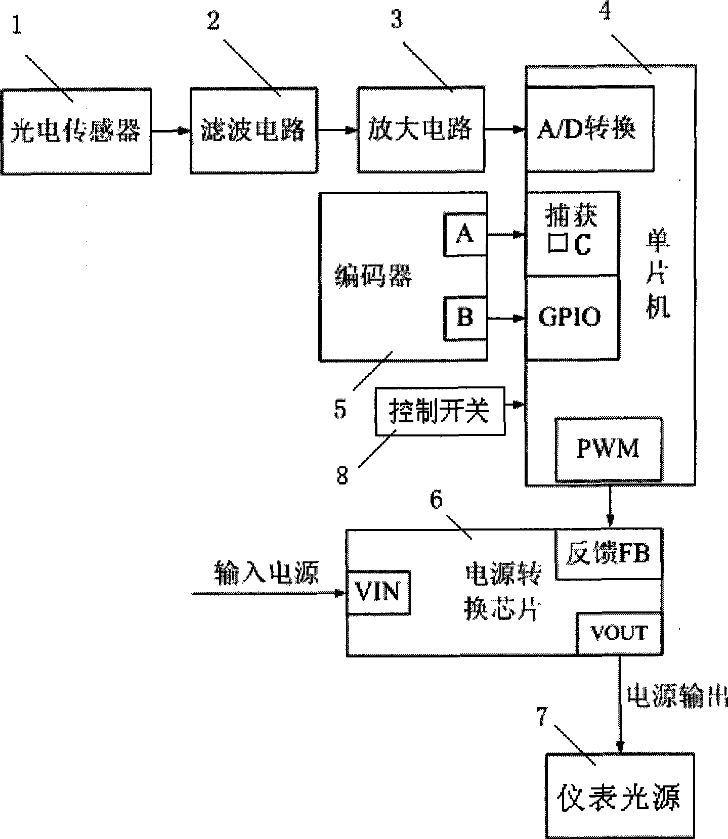
[0050] The difference from Embodiment 1 is that the automotive instrument display brightness adjustment device of this embodiment also includes a rotary encoder 5 and a control switch 8 . When the driver is dissatisfied with the automatically adjusted backlight brightness, he can manually rotate the encoder 5 to obtain a fine-tuning signal, thereby generating a change value △PWM, which is corrected on the basis of the original brightness displayed by the instrument. Wherein, the input end of the rotary encoder 5 is used to accept the external fine-tuning input, and the two pulse signals output by the output end are connected to a capture port C and a general purpose input / output port GPIO (general purpose input / output) of the single-chip microcomputer 4 respectively. The control switch 8 is coupled to the single-chip microcomputer 4, and the single-chip microcomputer 4 responds or shields the two-way pulse signals output by the rotary encoder 5 according to the state of the con...


PUM


Abstract

The invention discloses a display brightness adjusting device for motormeters. The device comprises a photoelectric sensor for converting sensed brightness of ambient light into a corresponding electric signal to be output; a processor for making a response to the electric signal output by the photoelectric sensor and outputting a corresponding control signal; and a power conversion module for making a response to the control signal output by the processor and outputting a corresponding voltage signal to a display motormeter. The invention also discloses a display brightness adjusting method for the motormeters. The adjusting device and the adjusting method overcomes the drawbacks of the prior motormeter that the display brightness is fixed or only can be manually and roughly adjusted by few grades, and can adjust the display brightness of the motometers to the best as well as saves energy effectively.

Description

【Technical field】 [0001] The invention relates to a device and a method for adjusting the display brightness of an automobile instrument, in particular to a device and a method for adjusting the brightness of the display of an automobile instrument according to the brightness of the environment and the driver's own requirements. 【Background technique】 [0002] In order to enable the driver to know the working conditions of the car and various systems at any time, the instrument panel in front of the driver is equipped with various indicating instruments such as vehicle speed, rotation speed, fuel oil, and electric power, which display the status parameters of various important parts of the car and the operating parameters of the car. In order to make it easier for the driver to clearly know the working conditions of the indicating instrument under relatively dark conditions, the indicating instrument usually includes an instrument display panel and a light source. Usually, th...

Claims


Application Information

Patent Timeline
IPC IPC(8): B60Q3/04G12B11/00
Inventor 李亚敏祖波韩良海王燕兵
Owner BYD CO LTD
Learn More