Electric motor stator scanning detection apparatus

A motor stator, scanning detection technology, applied in the direction of measuring device, electric device, motor generator test, etc., can solve the problem of inability to judge the quality of the motor stator and so on

Active Publication Date: 2009-02-18
SHANGHAI AOBOOR ELECTRONICS
View PDF0 Cites 15 Cited by
  • Summary
  • Abstract
  • Description
  • Claims
  • Application Information

AI Technical Summary

Problems solved by technology

The above inspection can only judge the quality of the motor stator, but cannot judge

Method used


Image

  • Electric motor stator scanning detection apparatus
  • Electric motor stator scanning detection apparatus
  • Electric motor stator scanning detection apparatus

Examples


Embodiment 1

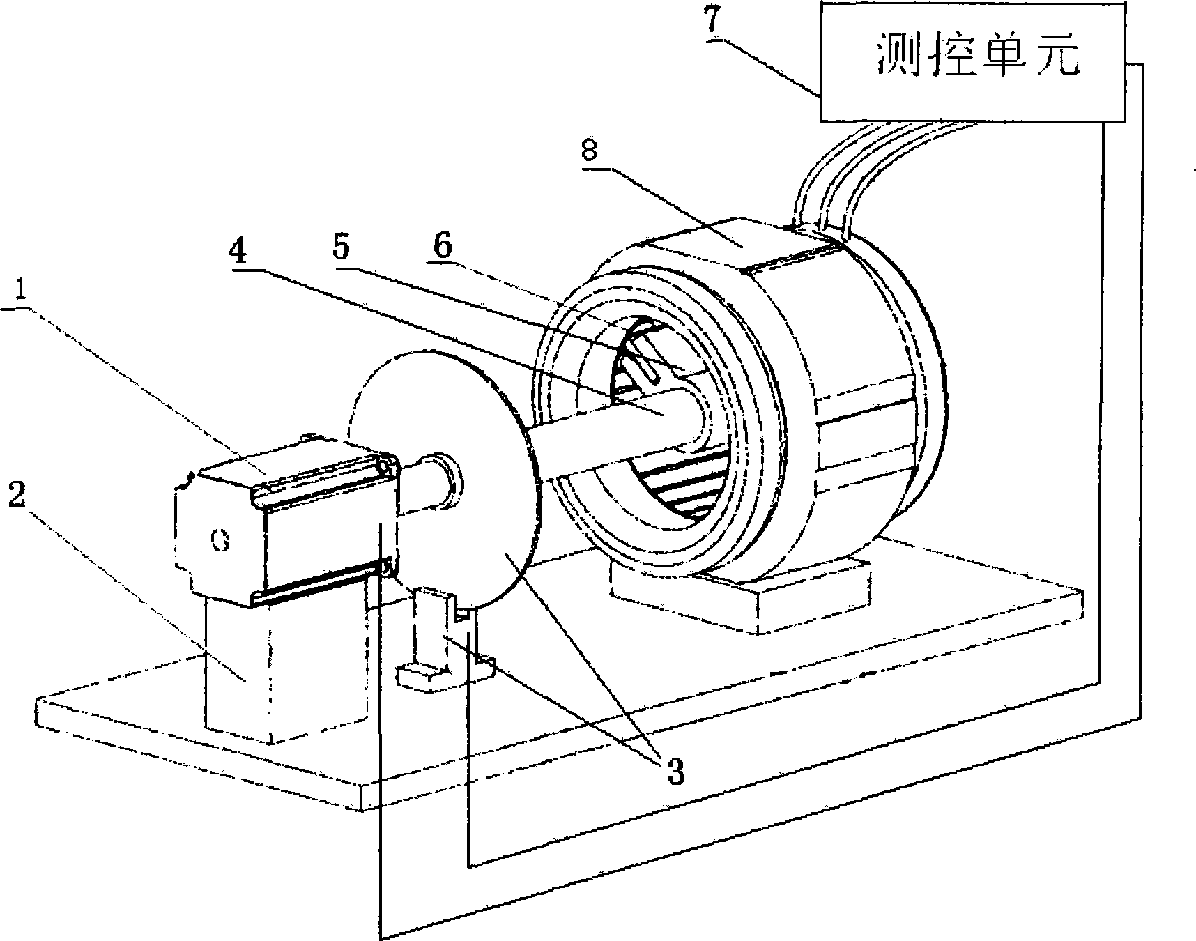
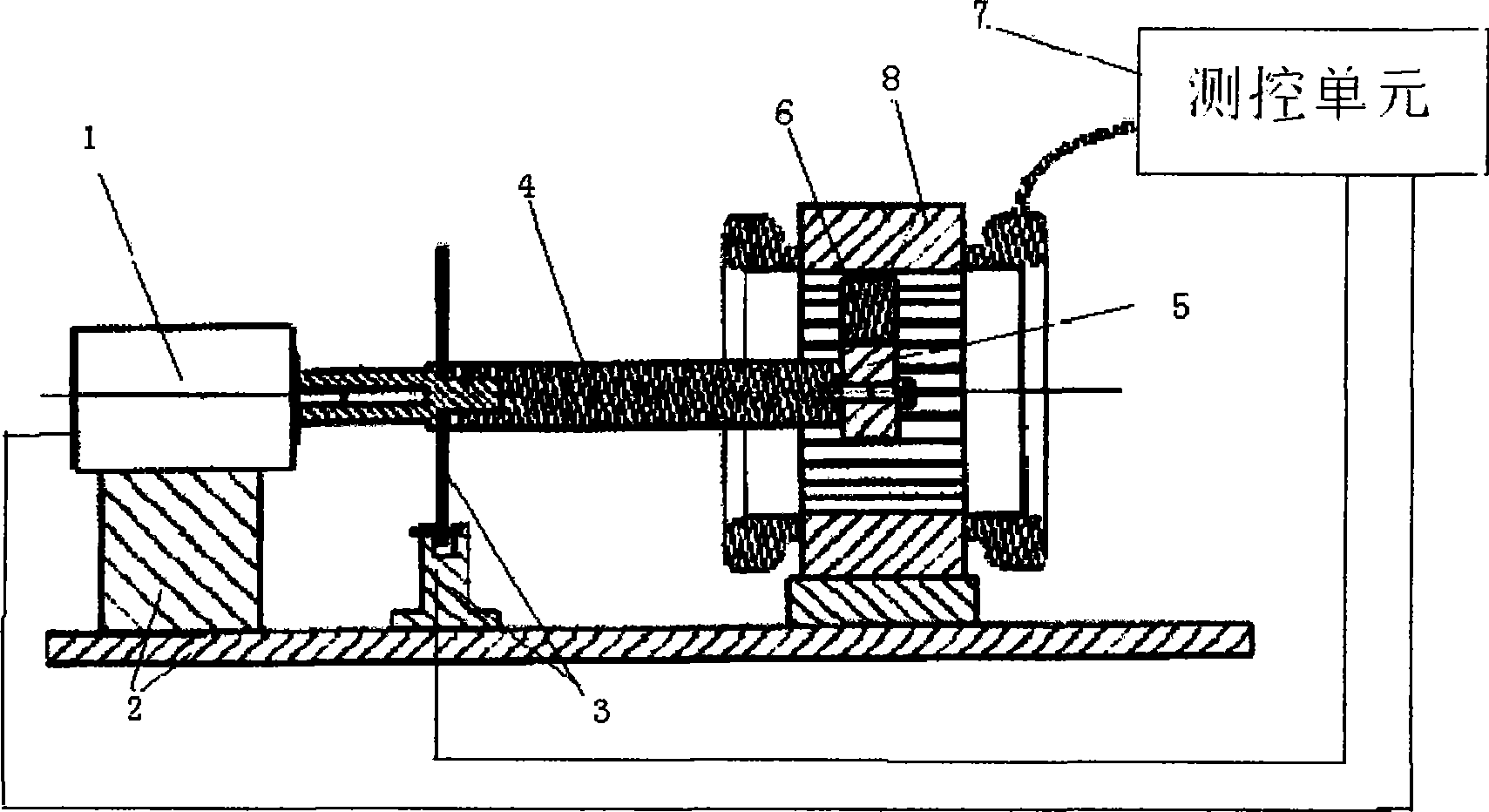
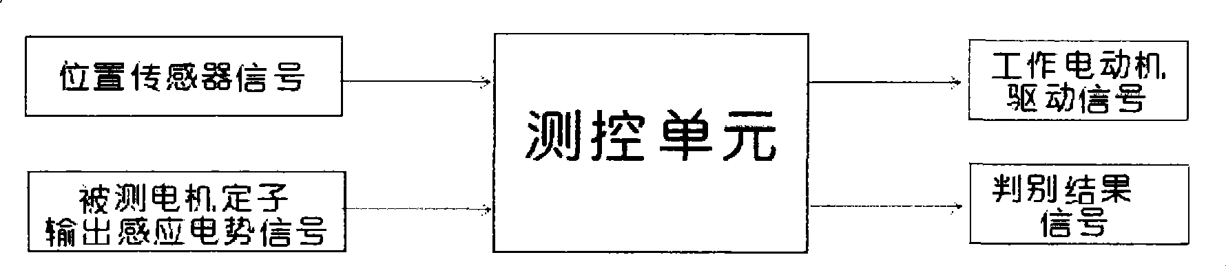
[0022] The motor stator scanning detection device of this embodiment consists of a working motor 1, a fixing frame 2, a position sensor 3 for detecting the azimuth angle, a coupling shaft 4 for connecting the rotating shaft of the working motor and the rotating body, and a fixing device for determining the detection position. The revolving body 5, a detecting magnet 6 for rotating and scanning around the stator axis of the motor under test, and a measurement and control unit 7 for detecting the induced electromotive force of the motor under test are formed. The working motor 1 is fixed on the fixed frame 2; the position sensor 3 is divided into two parts: a moving part and a position detecting part. Wherein, the moving part can be fixed on the rotating shaft or the coupling shaft 4 of the working motor 1, and the position detecting part is fixed on the fixing frame 2. The rotating body 5 is fixed on the rotating shaft or coupling shaft 4 of the working motor, and the detecting mag...

Embodiment 2

[0031] The basic structure of the motor stator scanning detection device of this embodiment is the same as that of the first embodiment. The only difference is that this embodiment uses the rotating shaft of the working motor 1, the coupling shaft 4 and the revolving body 5 to drive the detection magnet 6 along the stator of the motor under test. Rotate scanning of the outer wall surface, see Figure 5.

Embodiment 3

[0033] The motor stator scanning detection device of this embodiment is a device suitable for detecting the stator of a large motor. A motor stator scanning detection device, including a working motor 1, a movable positioning bracket 2'of the working motor, a position sensor 3 for detecting the azimuth angle, a coupling shaft 4 for connecting the rotating shaft of the working motor and a rotating body, and a fixed detecting magnet 6, the adjustable revolving body 5', the detecting magnet 6 for rotating and scanning around the stator of the motor under test, and the measurement and control unit 7 for testing the electromotive force of the stator 8 of the motor under test; characterized in that: the working motor 1 moves through the working motor The positioning bracket 2'is fixed inside the stator of the motor under test; the position sensor 3 is divided into two parts, a moving part and a position detection part, which are respectively fixed on the rotating shaft or coupling shaft...


PUM


Abstract

The invention relates to a scan detection device for a motor stator, which uses a working motor to drive a detecting magnet to rotate and scan along the near surface of the motor stator being detected, and the magnetic flux variety of the detected motor stator generated by the rotation and canning makes the detected motor stator to generate induced electromotive force, and the quality of the detected stator can be determined through detecting the circumferential induced electromotive force distribution curve of the detected stator by a measurement control unit and comparing with the circumferential induced electromotive force distribution curve of the qualified stator with the same size. A realization method of the invention is as follows: the device is composed of a working motor, a fixing bracket, a position sensor, a coupling spindle, a gyrator body, the detecting magnet and the measurement control unit. The position sensor is divided into two parts of a moving component and a position detecting component, and two components are respectively fixed on a rotating shaft or the coupling spindle of the working motor and on the fixing bracket. The gyrator body is fixed on the rotating shaft or the coupling spindle of the working motor, and the detecting magnet is fixed on the gyrator body and near the surface of the detected motor stator. The detecting device not only can detect the malfunction of the stator, but also can indicate which position or azimuth has quality problem around the circumference of the stator.

Description

Technical field [0001] The invention relates to a detection device, in particular to a motor stator scanning detection device. It uses the working motor to drive the detection magnet to rotate and scan along the surface of the measured motor stator. The resulting change in the magnetic flux of the measured sub-winding causes the measured sub-winding to generate induced electromotive force. The measurement and control unit measures the measured sub-winding along the circumference. The induced electromotive force distribution curve is tested and compared with the induced electromotive force distribution curve along the circumference of the qualified stator of the same specification to judge the quality of the measured motor stator. Background technique [0002] A motor stator is usually composed of an iron core and a coil winding, and the coil winding is usually formed by connecting multiple coil units. In the stator manufacturing process, in addition to the deviation of the core m...

Claims


Application Information

Patent Timeline
IPC IPC(8): G01R31/34G01B7/00
Inventor 彭建学邹维克
Owner SHANGHAI AOBOOR ELECTRONICS
Why Eureka
Try Eureka