
CMOS image sensor package

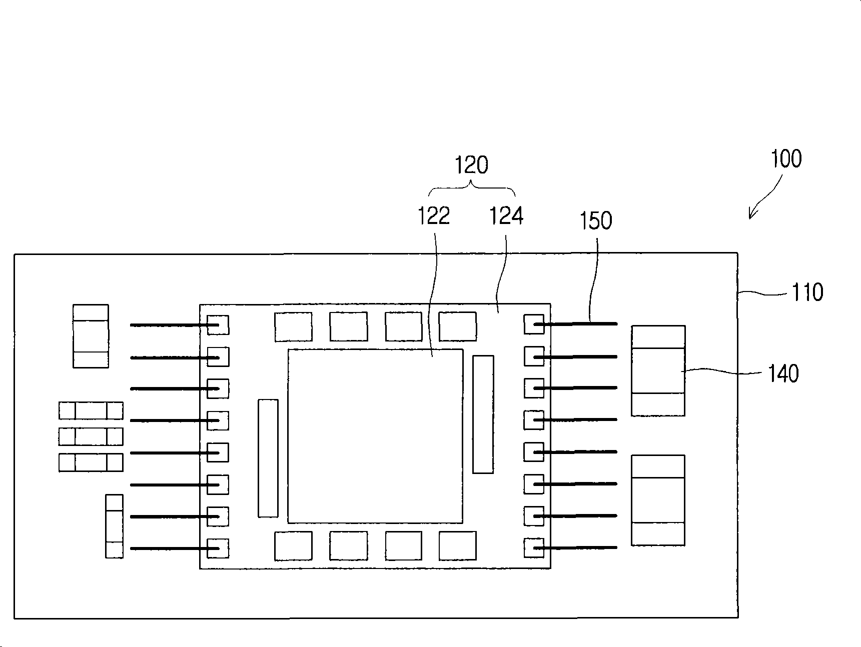
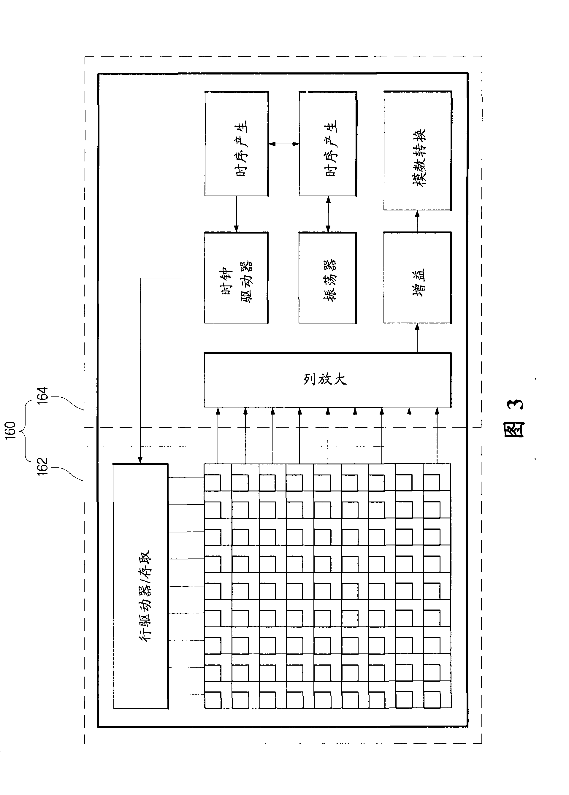
An image sensor, sensor technology, applied in the direction of image communication, electric solid-state devices, semiconductor devices, etc., can solve the problem of increasing the overall size of the CMOS image sensor chip

Inactive Publication Date: 2009-02-18
SAMSUNG ELECTRO MECHANICS CO LTD
View PDF1 Cites 5 Cited by
  • Summary
  • Abstract
  • Description
  • Claims
  • Application Information

AI Technical Summary

Problems solved by technology

In this way, it is possible to increase the overall size of the CMOS image sensor chips 120, 160 and the CMOS image sensor package 100

Method used


Image

  • CMOS image sensor package
  • CMOS image sensor package
  • CMOS image sensor package

Examples


Embodiment Construction

[0023] A CMOS image sensor package according to certain embodiments of the present invention will be described in more detail below with reference to the accompanying drawings. Those components that are identical or corresponding are given the same reference numerals regardless of the numerals of the figures, and redundant explanations are omitted.

[0024] Figure 4 is a cross-sectional view showing a CMOS image sensor package according to an embodiment of the present invention, Figure 5 is a plan view showing a CMOS image sensor package according to an embodiment of the present invention, and Image 6 is a schematic diagram showing a unit sensor in a pixel array sensor of a CMOS image sensor package according to an embodiment of the present invention.

[0025] exist Figure 4 to Figure 6 In, a CMOS image sensor package 300, a substrate 310, a circuit pattern 316, a via 318, cavities 312, 314, a pixel array sensor 320, a unit sensor 320' of the pixel array sensor, a pixel...


PUM


Abstract

A CMOS image sensor package is disclosed. The CMOS image sensor package includes: a substrate, on which a pre-designed circuit pattern is formed, and in which a cavity is formed; a pixel array sensor, which is electrically connected with the circuit pattern and stacked on one side of the substrate; and a control chip, which is electrically connected with the circuit pattern and held within the cavity. According to certain aspects of the invention, the CMOS image sensor chip can be separated into the pixel array sensor and the control chip, with the control chip and passive components embedded in cavities formed in the substrate, so that the size of the chip mounted on the substrate may be reduced, and consequently the overall size of the CMOS image sensor package may be reduced.

Description

[0001] Cross References to Related Applications [0002] This application claims priority from Korean Patent Application No. 10-2007-0082912 filed with the Korean Intellectual Property Office on Aug. 17, 2007, the disclosure of which is hereby incorporated by reference in its entirety. technical field [0003] The present application relates to a CMOS image sensor package. Background technique [0004] Image sensor chips are semiconductor devices that convert optical images into electrical signals. Examples of typical image sensor components include charge-coupled devices (CCDs) and CMOS image sensors. [0005] The CMOS image sensor sequentially detects output using a control circuit and a signal processing circuit located around MOS transistors, the number of which is equal to the number of pixels, and employing a switching technique using MOS transistors. [0006] With increasing demands for a greater variety of functions, smaller size, and lower cost in digital camera m...

Claims


Application Information

Patent Timeline
IPC IPC(8): H01L25/00H01L25/16H01L27/146H01L27/14H04N5/335H04N5/374H04N5/378
CPCH01L2924/19105H01L27/14618H01L2224/48091H01L2224/73265H01L2224/49175H01L2224/48227H01L2924/13091H01L2224/05553H01L2924/00014H01L2924/00
Inventor 权宁度李星金弘源
Owner SAMSUNG ELECTRO MECHANICS CO LTD
Learn More