Method for measuring iso system

A measurement method and different system technology, applied in the direction of code division multiplexing system, electrical components, wireless communication, etc., can solve the problems of inability to carry out business, sacrifice support, restriction, etc., achieve more convenience and flexibility, and improve performance Effect

Inactive Publication Date: 2009-02-25
TD TECH COMM TECH LTD
View PDF0 Cites 9 Cited by
  • Summary
  • Abstract
  • Description
  • Claims
  • Application Information

AI Technical Summary

Problems solved by technology

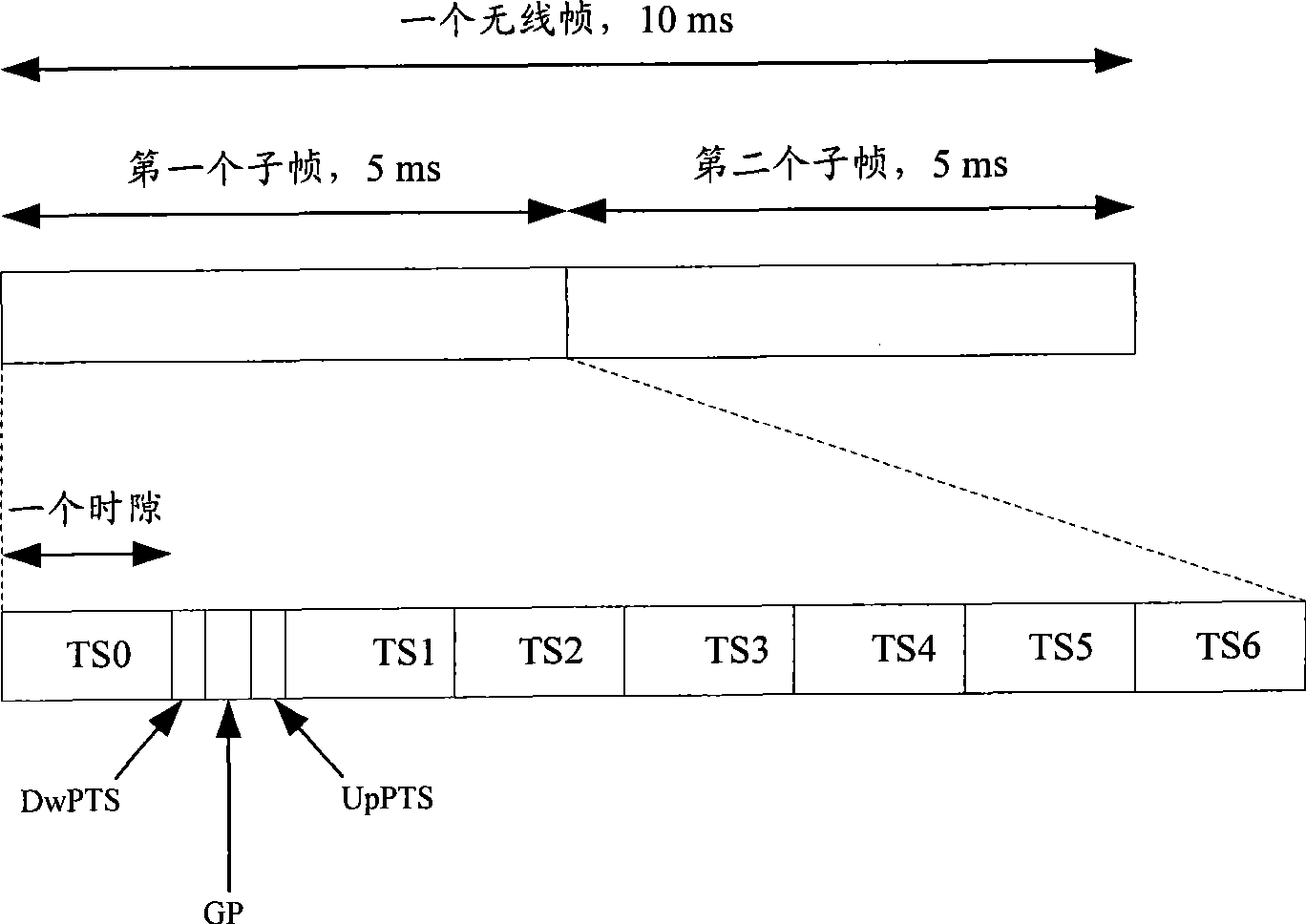
[0010] However, since some services need to occupy several consecutive time slots, for example, some services with a large amount of data usually need to occupy several consecutive time slots, and the above method allocates 3 consecutive idle time slots in each subframe. The time slot is used for different system measurement, which will inevitably make those services that need to occupy continuous time slots impossible, thus greatly limiting the business that can be supported by this method for different system measurement
It can be seen that, in order to support the measurement of different systems, the above existing methods sacrifice the support for normal business, and the performance is poor.

Method used


Image

  • Method for measuring iso system
  • Method for measuring iso system
  • Method for measuring iso system

Examples


Embodiment 1

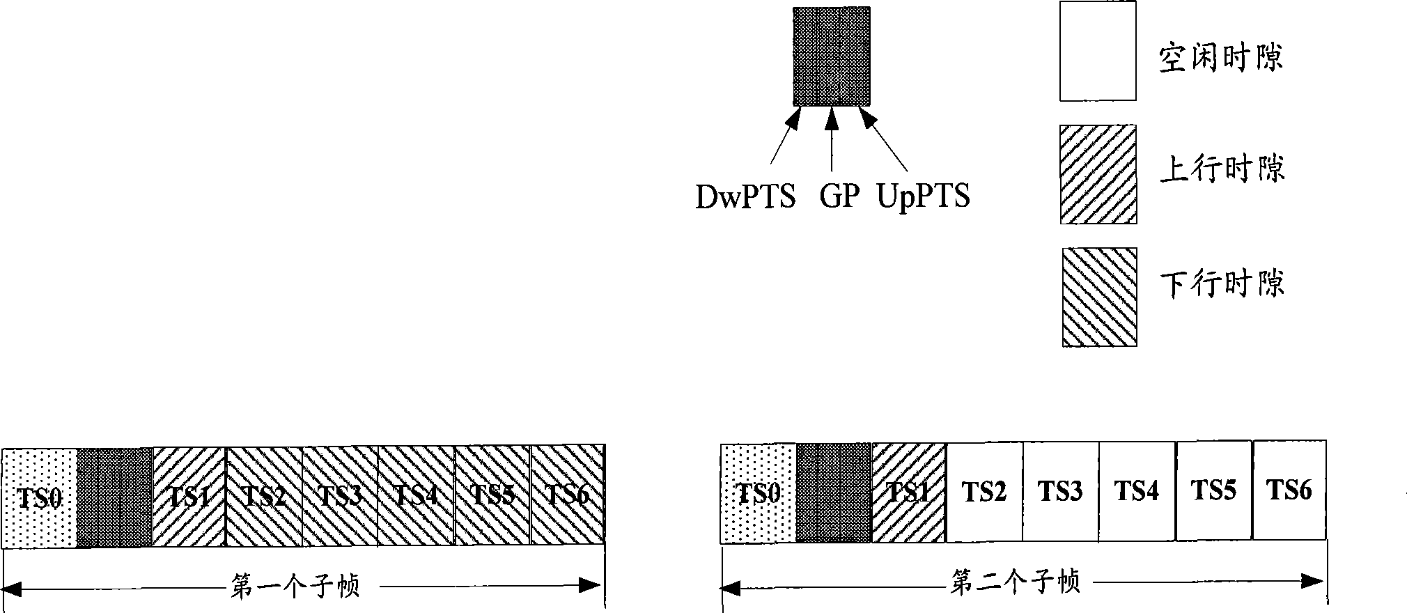
[0054] This embodiment corresponds to the first method described above. Since in the prior art, the time slots in the first subframe of the radio frame are usually allocated, and the time slot allocation in the second subframe is the same as that in the first subframe, therefore, the method is specifically implemented There are two possible implementations:

[0055] The first way: allocate at least 4 consecutive time slots as free time slots in the first subframe

[0056] At this time, the DPCH information sent by the network side control entity to the UE needs to carry the time slot number corresponding to the idle time slot in the first subframe, and use it as the downlink time slot / uplink time slot in the second subframe. Indicates the slot number to inform the UE that the slot allocation in the second subframe is different from that in the first subframe, and the slot number corresponding to the idle slot in the first subframe is used for uplink in the second subframe Th...

Embodiment 2

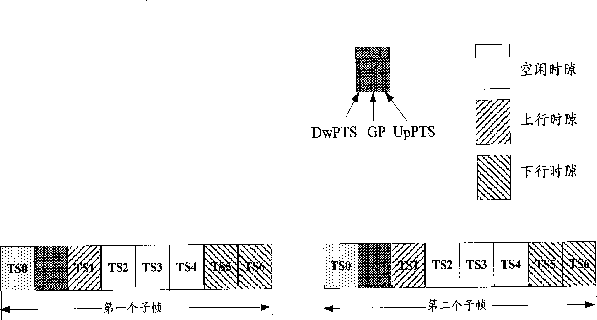
[0074] This embodiment corresponds to the second method described above. Figure 4 A schematic diagram of the frame allocation structure in Embodiment 2 of the present invention is shown. see Figure 4 In this embodiment, 2 radio frames are used as the repetition period, and at least 4 consecutive time slots in the first subframe and the second subframe of the second radio frame of every 2 radio frames are used as idle time slots.

[0075] Such as Figure 4 Shown: In this method, TS1 of the first wireless frame is used as the uplink time slot, TS2~TS6 are used as the downlink time slot, and the same method is used for the first subframe and the second subframe to allocate time slots; the second TS1 of the first radio frame is used as an uplink time slot, TS2~TS6 are used as idle time slots, and the same method is used to allocate time slots for the first subframe and the second subframe. That is to say, for the downlink, the DPCH repetition period is 2 radio frames, and the...


PUM


Abstract

The invention discloses a method for measuring different systems, which includes the following steps: among one subframe of wireless frames, distributing at least four continuous time slots as free time slots; measuring the different systems at the free time slot. The invention also discloses another different system measurement method, which includes the following steps: for one wireless frame of every Nth wireless frames, distributing at least four continuous time slots as free time slots among the two subframes of one wireless frame; the N is an integer which is more than or equal to 2; carrying out the different system measurement at the free time slot. The invention has the advantages that: more different system measurement samples can be obtained with less time slots cost, and different system is measured and normal business is provided.

Description

technical field [0001] The invention relates to different system handover technology, in particular to a different system measurement method. Background technique [0002] With the maturity of the third generation mobile communication (3G) technology, many countries in the world have deployed 3G systems; however, for a long period of time, the second generation mobile communication (2G) system and 3G system will co-exist, Complement each other. In this case, it is necessary and unavoidable to support user terminal (UE) inter-system handover (also called inter-system handover) from 3G to 2G. In order to support the inter-system handover function from 3G to 2G, UE should have the ability to measure and evaluate the wireless signal quality of 2G neighboring cells in the monitored set (monitored set) under the control of the 3G system network side control entity; and the network side control The entity needs to control the UE to perform measurement at an appropriate measuremen...

Claims


Application Information

Patent Timeline
Patent Type & Authority Applications(China)
IPC IPC(8): H04Q7/34H04Q7/38H04J13/02H04W24/08H04W72/08
Inventor 郭伟丁欣章小平
Owner TD TECH COMM TECH LTD
Why Eureka
Try Eureka