Video-assisted laryngeal mask airway devices

一种气道、喉罩的技术,应用在喉罩气道设备领域

Inactive Publication Date: 2009-02-25
EZC HLDG
View PDF6 Cites 15 Cited by
  • Summary
  • Abstract
  • Description
  • Claims
  • Application Information

AI Technical Summary

Problems solved by technology

However, all these devices suffer from the aforementioned disadvantages
Specifically, none of these devices provide an adequate degree of ventilation for the patient while the intubation procedure is in progress

Method used


Image

  • Video-assisted laryngeal mask airway devices
  • Video-assisted laryngeal mask airway devices
  • Video-assisted laryngeal mask airway devices

Examples


Embodiment Construction

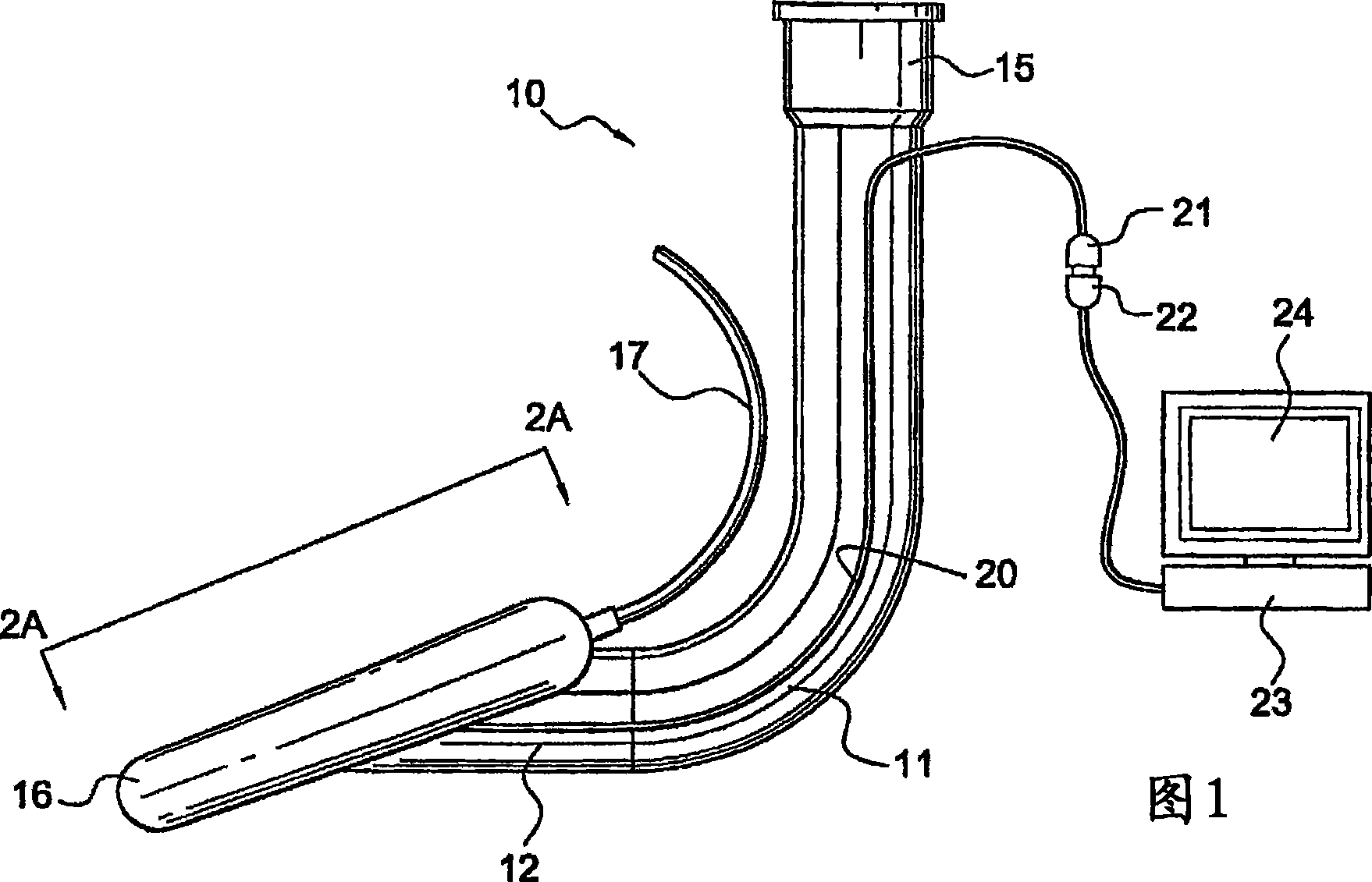
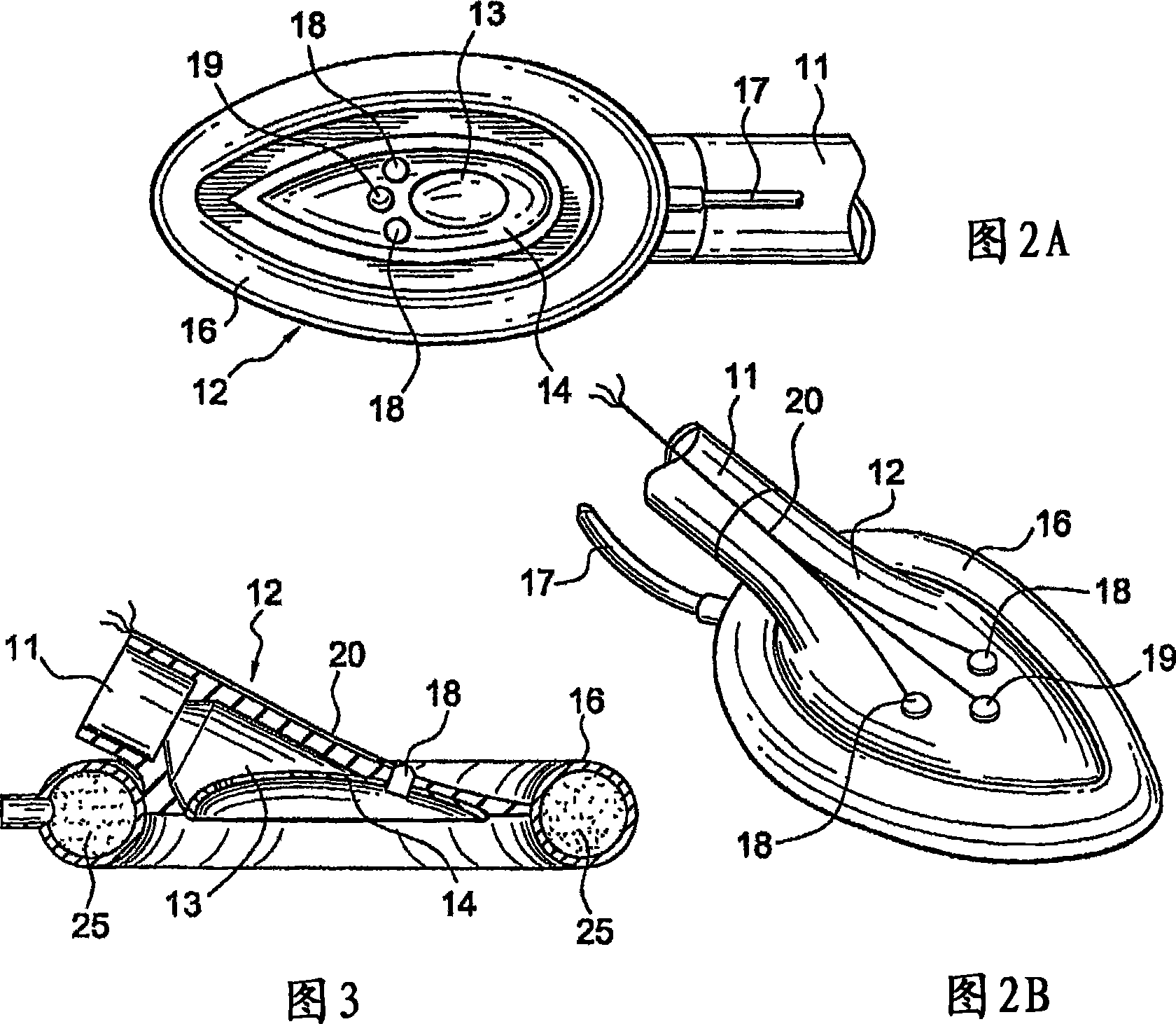
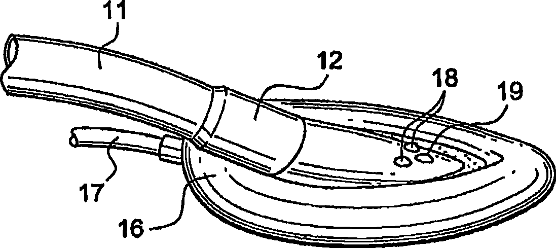
[0036] In accordance with the principles of the present invention, a video laryngeal mask airway ("LMA") device for facilitating lung ventilation of an unconscious patient is provided that includes an airway tube and a mask attached to a tip of the airway tube. The mask communicates with the airway tube and includes a peripheral cuff configured to fit and easily fit into the space behind the larynx. In this way, the cuff forms a seal around the circumference of the laryngeal entrance and prevents penetration of the device into the interior of the larynx. According to an aspect of the invention, the mask carries at least one video sensor having a field of view that includes the laryngeal entrance when the mask is inserted into the patient's airway. The LMA device, which may be configured as an LMA or ILM, is preferably disposed of after a single use. Alternatively, the LMA device may have the video sensor oriented in the mask portion so as to provide the desired view of other ...


PUM


Abstract

A laryngeal mask airway device is provided that incorporates a video sensor, such as a CCD, CMOS or NMOS imaging chip, arranged to provide an image of the laryngeal inlet or other airway structures. The video sensor is electrically coupled to a reusable processing unit that receives the signals generated by the video sensor and generates a digital image of the interior of the patient's airway, thereby enabling the clinician to have immediate optical confirmation of the position of the mask aperture relative to the laryngeal inlet from the moment of insertion of the device.

Description

technical field [0001] The present invention relates to a laryngeal mask airway device for administering anesthesia, such as a laryngeal mask airway and an intubated laryngeal mask, having one or more video sensors mounted in the bowl portion of the device to aid in placement of the device or insertion Endotracheal tube. Background technique [0002] A laryngeal mask airway ("LMA") is known to administer anesthesia in place of or in conjunction with an endotracheal tube. The LMA allows the patient to ventilate without inserting an endotracheal tube into the trachea, but does not prevent the risk of reflux and aspiration. Commercially available LMAs are designed to reduce the risk encountered with endotracheal tubes of incorrect placement of the tube into the esophagus instead of into the trachea and are now used in more than 1 / 3 of all anesthesia procedures. Such devices typically include a flexible conduit connected to and in communication with a mask portion that include...

Claims


Application Information

Patent Timeline
Patent Type & Authority Applications(China)
IPC IPC(8): A61M16/00A61B1/267A62B18/08
CPCA61B1/06A61M16/0445A61M16/0488A61M2016/0409A61M2016/0445A61B1/267A61M16/0409A61M16/04A61M16/0436
Inventor R·格拉森伯格Z·金梅尔
Owner EZC HLDG
Why Eureka
Try Eureka