Method for manufacturing plastic component assembly and plastic component assembly, and plastic component-welded head and plastic component welding machine

A technology of a plastic part and a manufacturing method, which is applied in the fields of plastic part welding heads and plastic part welding machines, can solve the problems of uneven joint strength, high cost of tap screws, and difficulty in improving the productivity of plastic part assemblies, and achieves the improvement of joint strength. Effect

Inactive Publication Date: 2009-02-25
VICTOR ADVANCED MEDIA CO LTD
View PDF0 Cites 5 Cited by
  • Summary
  • Abstract
  • Description
  • Claims
  • Application Information

AI Technical Summary

Problems solved by technology

[0004] The joint between a pair of plastic parts formed by this type of screw fastening has the advantage of strong mutual joint strength, but there is a problem that the more screw fastening places are, the higher the cost of the tap screw is.
In addition, although the work of screw fastening is mostly automated, there is a problem that it is difficult to improve the productivity of plastic parts assemblies due to the long working time of screw fastening.
Furthermore, when the accuracy of the screw fastening work, that is, the degree of screw fastening fluctuates, there is a problem that the joint strength at a plurality of screw fastening locations becomes uneven, and there is a possibility of causing problems in the quality of the plastic parts assembly. sex
In the conventional bonding method using ultrasonic welding, the bonding strength that can pass the reliability test cannot be obtained, and a bonding method using ultrasonic welding (or thermal fusion bonding) that can greatly improve the bonding strength is required

Method used


Image

  • Method for manufacturing plastic component assembly and plastic component assembly, and plastic component-welded head and plastic component welding machine
  • Method for manufacturing plastic component assembly and plastic component assembly, and plastic component-welded head and plastic component welding machine
  • Method for manufacturing plastic component assembly and plastic component assembly, and plastic component-welded head and plastic component welding machine

Examples


no. 1 example

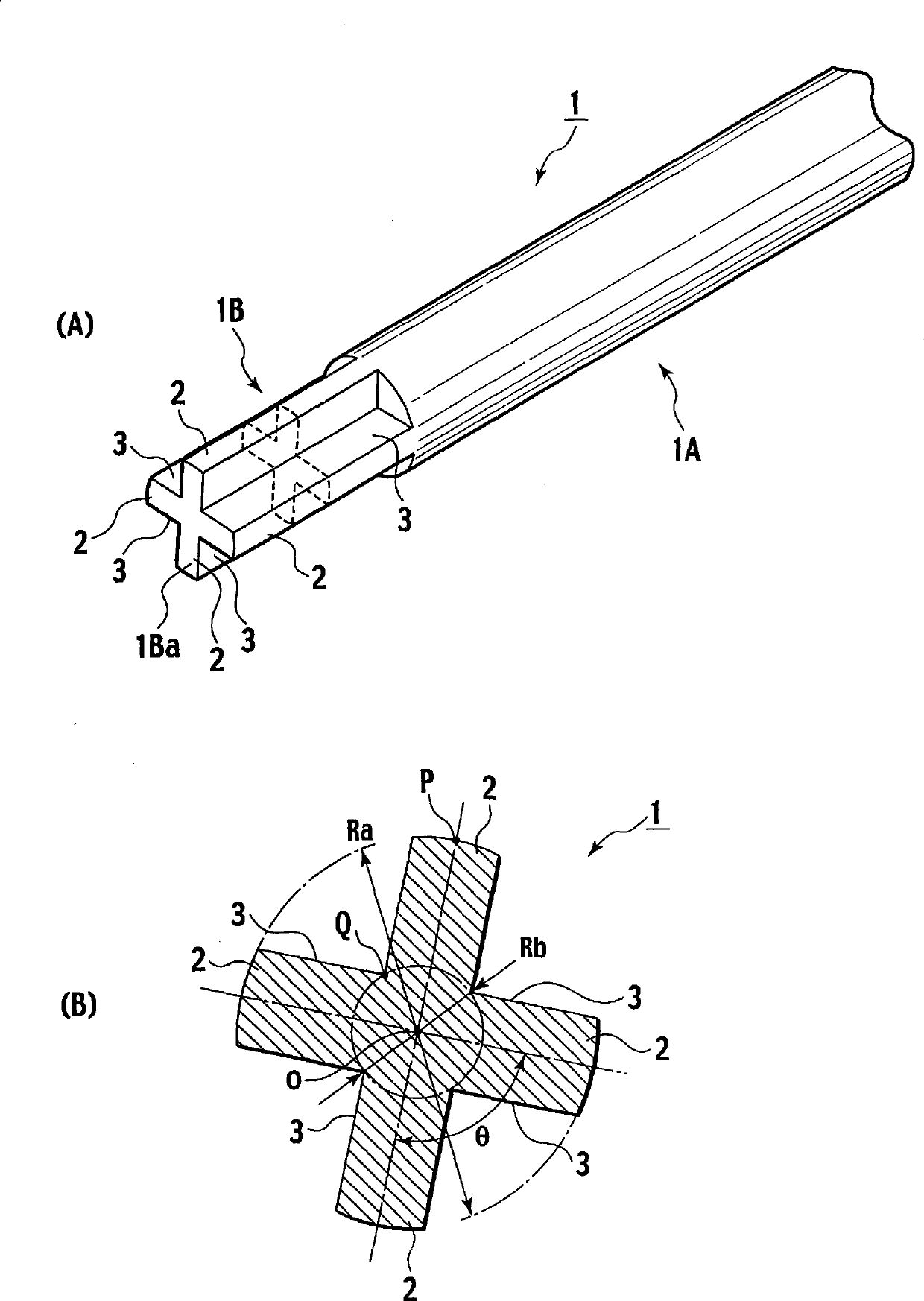
[0056] image 3 Shown is a first embodiment of a plastic component welding head (hereinafter simply referred to as a welding head) for realizing the method of manufacturing a plastic component assembly of the present invention. image 3 (A) is a perspective view showing the welding head 1 of the first embodiment, image 3 (B) is in image 3 (A) Cross-sectional view of the portion indicated by the dotted line.

[0057] like image 3 (A), image 3 As shown in (B), the outer shape of the welding head 1 is substantially cylindrical, and has a cylindrical root portion 1A and a concave-convex front end portion 1B unique to the first embodiment described later. The front end portion 1B is integrally connected to the root portion 1A. The front end portion 1B is substantially cross-shaped when viewed from the front end surface 1Ba. That is, the tip portion 1B of the welding head 1 includes four protrusions 2 protruding radially from the center of the cylinder and four recesses 3 ...

no. 2 example

[0074] Figure 9 A second embodiment of a welding head for realizing the method of manufacturing a plastic component assembly of the present invention is shown. Figure 9 (A) is a perspective view showing the welding head 11 of the second embodiment, Figure 9 (B) is a side view of the welding head 11 . For the description of the functions and effects of the second embodiment, components that have the same functions and effects as those of the first embodiment are appropriately omitted. In addition, the examples of the preferred configurations described in the first embodiment are similarly applicable in the second embodiment, so descriptions thereof will be appropriately omitted.

[0075] like Figure 9 (A), Figure 9 As shown in (B), the outer shape of the welding head 11 is substantially cylindrical, and has a cylindrical root portion 11A and a tip portion 11B having a shape specific to the second embodiment described later. The front end portion 11B is integrally conn...

no. 3 example

[0085] Figure 10 A third embodiment of a welding head for realizing the method of manufacturing a plastic component assembly of the present invention is shown. Figure 10 (A) is a perspective view showing the welding head 21 of the third embodiment, Figure 10 (B) is a plan view of the welding head 21 viewed from the front end side, Figure 10 (C) is from Figure 10 Arrows X1 and X2 of (B) observe the top view of the welding head 21, Figure 10 (D) is to use will Figure 10 (B) A cross-sectional view of the welded joint 21 cut along a line connected by arrows Y1 and Y2 . For the description of the functions and effects of the third embodiment, the parts that have the same functions and effects as those of the first and second embodiments are appropriately omitted. In addition, since the example of the preferred configuration described in the first embodiment is similarly applicable to the third embodiment, description thereof is appropriately omitted.

[0086] like Fi...


PUM


Abstract

This invention provides a plastic component of which the lower half (102) and upper half (103) are thermoplastic. A welding head (1), which is longitudinally extended by a predetermined length range and is provided with a plurality of convexes in the circumferential direction, is inserted so as to lie astride a lower boss (107) and an upper boss (110) in a joint (105). The plastic in the joint (105) is melted by the welding head (1). The melted plastic is solidified to weld and integrate the lower half (102) and the upper half (103) to each other.

Description

technical field [0001] The present invention relates to a method of manufacturing a plastic part assembly for joining a pair of thermoplastic parts to form a plastic part assembly, a plastic part assembly in which a pair of thermoplastic parts are joined, and an A plastic part welding head and a plastic part welding machine for joining a pair of plastic parts. Background technique [0002] Tape-shaped recording media such as video tapes and audio tapes are usually housed in cases made of plastic components, and disk-shaped recording media such as optical discs and magneto-optical disks are sometimes housed in cases made of plastic parts. An object containing a tape-shaped recording medium in a case is called a tape cassette, and an object containing a disc-shaped recording medium in a case is called a disk case. Hereinafter, the plastic parts for storing objects are referred to as storage containers. [0003] This type of storage container is usually composed of a pair of ...

Claims


Application Information

Patent Timeline
Patent Type & Authority Applications(China)
IPC IPC(8): B29C65/08G11B23/113
CPCB29C65/8223B29C65/08B29C66/80B29C65/8207B29C66/21B29C65/02B29C66/54B29C66/81463B29L2017/008B29K2101/12G11B23/113B29C66/8322G11B23/08785B29C66/542B29C66/73921B29C66/81429Y10T428/24322B29C65/00
Inventor 铃木和彦
Owner VICTOR ADVANCED MEDIA CO LTD
Why Eureka
Try Eureka