

Radio communication device, frequency band setting system
A wireless communication device and frequency band setting technology, applied in wireless communication, transmission system, selection device, etc., can solve problems such as not meeting the minimum requested frequency band, unable to receive content, etc.
- Summary
- Abstract
- Description
- Claims
- Application Information
AI Technical Summary
Problems solved by technology
Method used
Image

Examples
Embodiment approach 1
[0112]
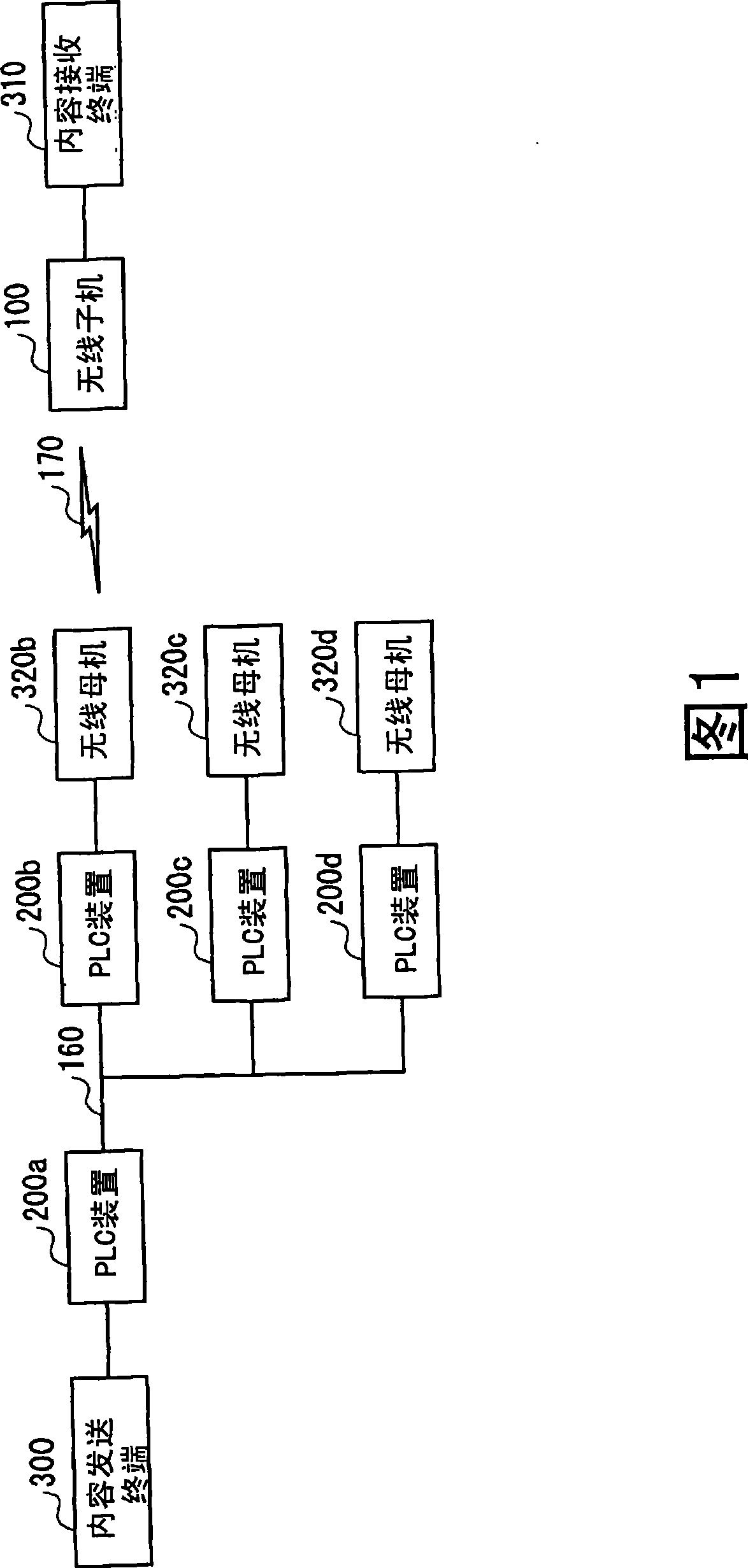
[0113] FIG. 1 is a system diagram showing a system configuration of a frequency band setting system. As shown in the figure, the frequency band setting system includes a wireless slave unit 100, PLC (Power Line Communication) devices 200a, 200b, 200c, and 200d, a content transmitting terminal 300, a content receiving terminal 310, and wireless master units 320b and 320c , 320d to form. As shown in FIG. 1 , the content transmission terminal 300 is wired to the PLC device 200a. In addition, the PLC devices 200a, 200b, 200c, and 200d are connected to each other through a power line network, and QoS settings can be performed. As shown in the figure, the PLC device 200b and the wireless master machine 320b, the PLC device 200c and the wireless master machine 320c, and the PLC device 200d and the wireless master machine 320d are paired. In this figure, the wireless slave device 100 is wirelessly connected to the wireless master device 320 b and is paired with the conten...
Embodiment approach 2
[0215] In the above-mentioned embodiment, when the setting between the PLC devices fails, the PLC device itself proposes a new route to the wireless slave unit. Here, after that, that is, after the wireless slave unit switches the wireless master unit for frequency band setting, the content transmission terminal fails to perform the QoS setting between the PLC devices connected to the wireless master unit instead of the PLC device. Implementation of the following processing.
[0216]
[0217] FIG. 8 is a system diagram showing a system configuration of a frequency band setting system according to Embodiment 2. FIG. As shown in the figure, the frequency band setting system includes a wireless slave unit 400, PLC devices 500a, 500b, 500c, and 500d, a content transmitting terminal 600, a content receiving terminal 610, and wireless master units 620b, 620c, and 620d. The basic structure It is the same as that shown in Embodiment 1. Hereinafter, parts that are different from Em...
Embodiment approach 3
[0262] In Embodiments 1 and 2 above, a closed network is disclosed in which a content transmitting terminal and a content receiving terminal can always be connected to any wireless main unit with which the wireless slave unit is to be connected. However, in Embodiment 3, a case will be described in which a wireless master unit to which a wireless slave unit can be connected is not necessarily connectable to a content transmission terminal.
[0263]
[0264] The system configuration of this embodiment is shown in FIG. 13 . As shown in the figure, the frequency band setting system includes a wireless slave unit 700, PLC devices 800a, 800b, 800c, and 800d, a content transmitting terminal 900, a content receiving terminal 910, and wireless master units 920b, 920c, and 920d. The basic structure It is the same as that shown in Embodiment 1. Here, in addition to devices included in the frequency band setting system, as wireless masters to which the wireless slave 100 can be connec...
PUM
 Abstract
Description
Claims
Application Information