Helicopter rotor operation method and system

A helicopter rotor and control system technology, applied in the field of helicopter control, can solve the problems of actuators not working properly, no measurement and control scheme, no transmission mechanism, etc., shorten the development cycle, improve safety and survivability, and facilitate The effect of integration

A helicopter rotor and control system technology, applied in the field of helicopter control, can solve the problems of actuators not working properly, no measurement and control scheme, no transmission mechanism, etc., shorten the development cycle, improve safety and survivability, and facilitate The effect of integration

CN101376433AInactive Publication Date: 2009-03-04NANJING UNIV OF AERONAUTICS & ASTRONAUTICS

Image

  • Helicopter rotor operation method and system
  • Helicopter rotor operation method and system
  • Helicopter rotor operation method and system

Examples


Embodiment Construction

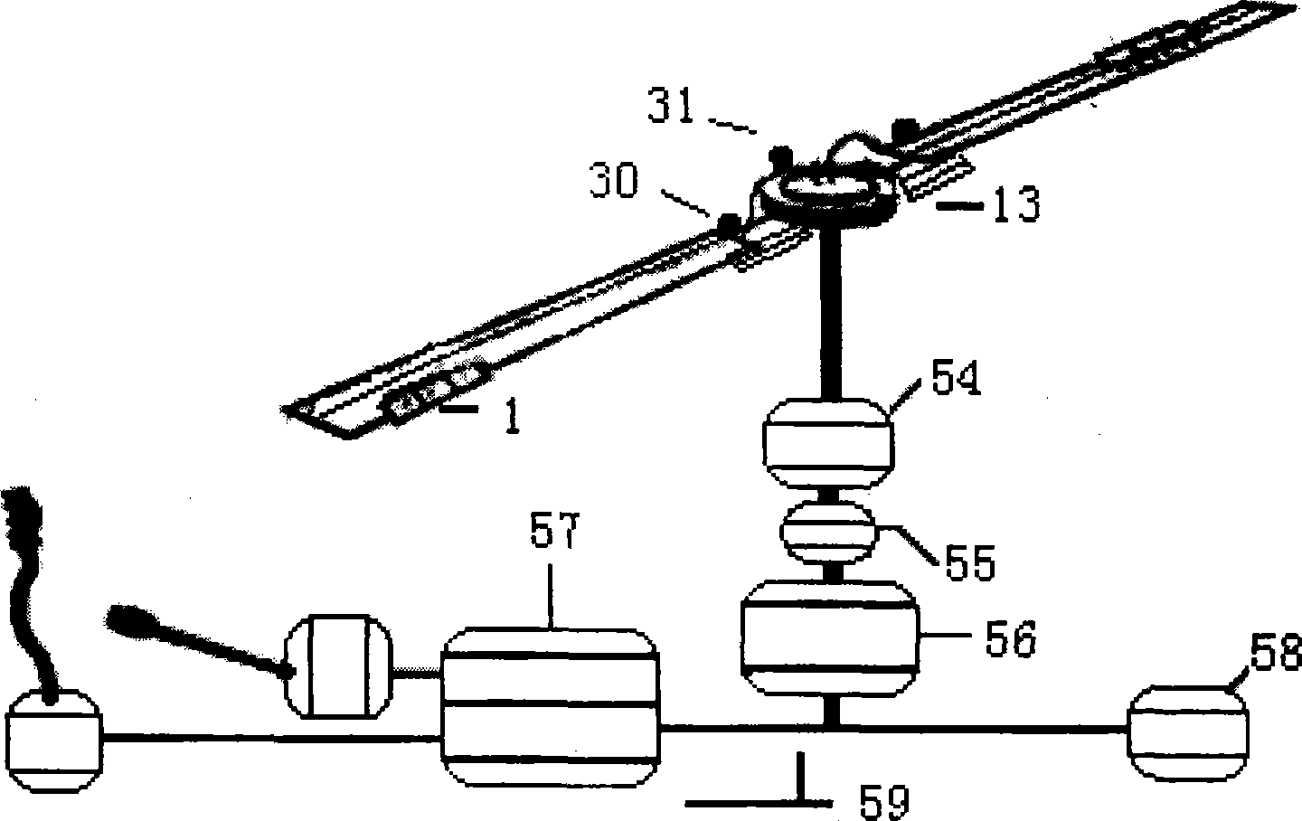
[0033] 1. Its basic principle of the present invention sees figure 1 As shown in the figure, the driver manipulates the joystick, and the control electric signal generated by the joystick outputs control instructions through the controller, passes through the power amplifier, collector ring, rotor shaft, and is transmitted to the swing electromagnetic actuator installed on the arm of the propeller hub. The oscillating electromagnetic actuator drives the transmission rod system located inside the blade, and drives the flaps at the trailing edge of each blade to do deflection motion; as long as the torsional stiffness of the blade root is appropriate, the pitching moment generated by the flaps will be generated by the aeroelastic action. Change the pitch of the blades, so as to realize the control without automatic tilter. At the same time, the pitch angle value is fed back to the controller in real time through the pitch angle sensor to compare with the control command to obtain...


PUM


Abstract

The invention relates to a control method and a system of a helicopter rotor, which belongs to the technical field of helicopter operation. The control method is characterized in that the distance changing of a blade is realized by adopting an actuator positioned on the stinger of each propeller boss to drive a flap positioned at the rear edge of the blade, so as to realize the control of a rotor system. The system comprises a demountable flap (1) installed at rear edge of the blade, torque soft propeller bosses (14), an actuator (13) installed on the stinger of torque soft propeller bosses, a flap control mechanism (1) with one end being connected with actuator (13) and the other end thereof being connected with the flap (1), and a test control system (59). The control method and the system have the advantages that the screw piston of each blade can be independently controlled, the structure is simple, the weight is light, the controllability is good, and the reliability and the security are high.

Description


Claims


Application Information

Patent Timeline
04 Mar 2009
Publication
CN101376433A