Uplink synchronization method, base station and customer equipment

A synchronous control, base station technology, applied in the direction of transmission control/equalization, communication between multiple stations, etc., can solve the problems of reduced code channel orthogonality, affecting reception quality, interference, etc., to improve reception performance, enhance The effect of orthogonality

Active Publication Date: 2009-03-18
北京万海云科技有限公司
View PDF0 Cites 71 Cited by
  • Summary
  • Abstract
  • Description
  • Claims
  • Application Information

AI Technical Summary

Problems solved by technology

[0007] Through the above process, it can be seen that when multiple uplink channels coexist in the same subframe or time slot, multiple timing advances will be generated, and these multiple timing advances may have different values. In this way, corresponding to different uplink The bursts sent by the channel on different code channels will not be aligned in time, especially for the situation where multiple uplink channels coexist in the same time slot. This problem is more prominent, which reduces the orthogonality between code channels and the mutual Interference will affect the quality of reception

Method used


Image

  • Uplink synchronization method, base station and customer equipment
  • Uplink synchronization method, base station and customer equipment
  • Uplink synchronization method, base station and customer equipment

Examples


example 1

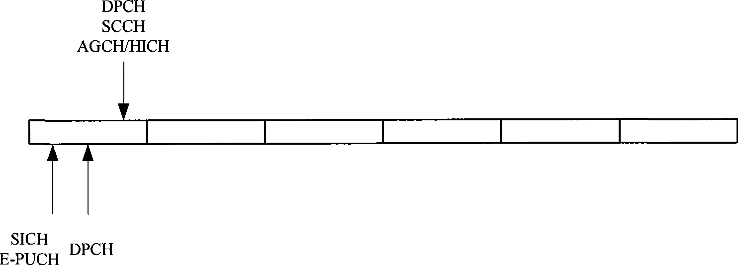
[0073] Example 1: If Figure 2a as shown, Figure 2a It is a schematic diagram of channel transmission in Example 1, and each cell in the figure represents a subframe. Wherein, the uplink and downlink channels are separated one by one, that is, there are both uplink channels and downlink channels in the same subframe. Figure 2a In , since multiple uplink channels are sent simultaneously in the first subframe, for the second subframe, one of these uplink channels can be selected as the current timing reference uplink channel, and the time of the uplink channel The advance amount is used as the unified advance amount of each channel at present. Alternatively, the weighted average of the timing advances of these uplink channels may also be used as the unified advance of each current channel.

example 2

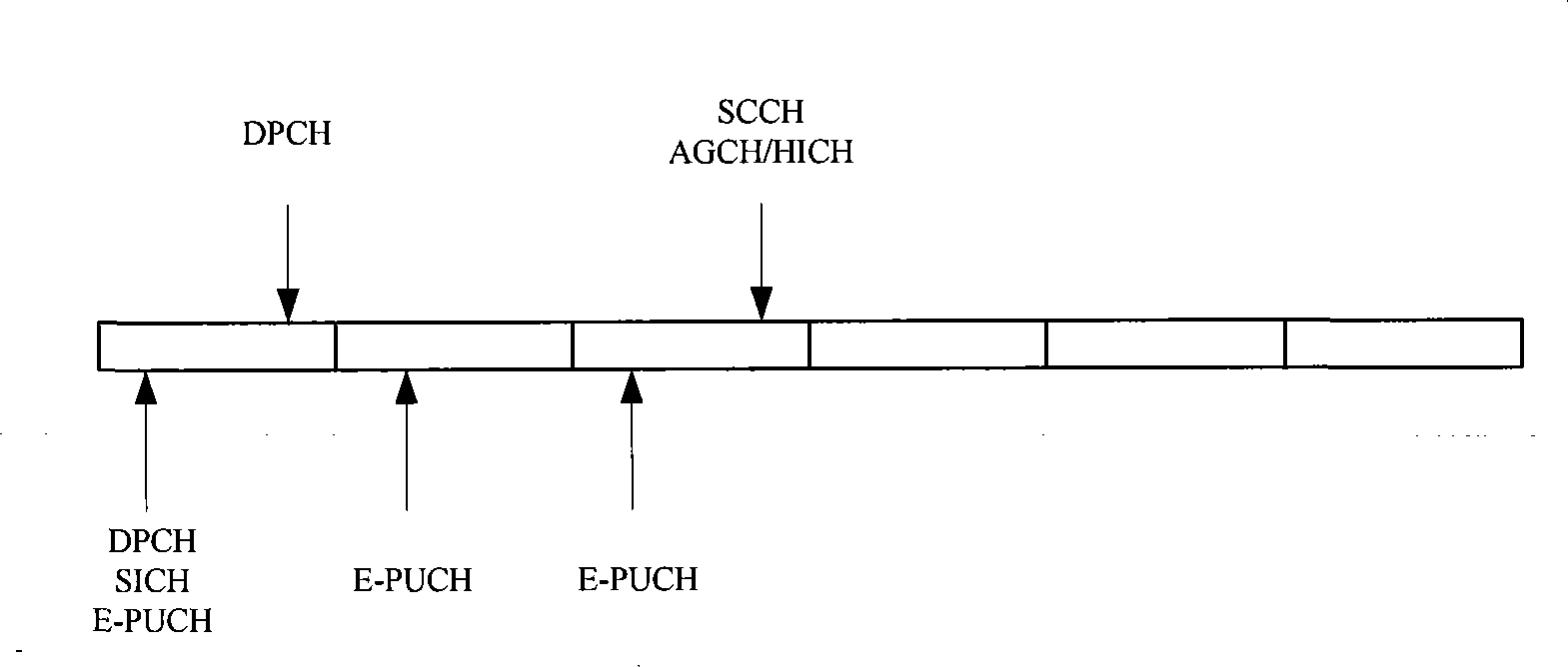
[0074] Example 2: If Figure 2b as shown, Figure 2b It is a schematic diagram of channel transmission in Example 2, and each cell in the figure represents a subframe. Wherein, the number of uplink subframes is greater than the number of downlink subframes. Figure 2b , since only the E-PUCH is sent in the third subframe, for the fourth subframe, the E-PUCH can be used as the current timing reference uplink channel, and the timing advance of the E-PUCH can be used as the current channel uniform advance.

example 3

[0075] Example 3: If Figure 2c as shown, Figure 2c It is a schematic diagram of channel transmission in Example 3, and each cell in the figure represents a subframe. Wherein, the number of downlink subframes is greater than the number of uplink subframes. Figure 2c , since only the E-PUCH is sent in the fifth subframe, for the sixth subframe, the E-PUCH can be used as the current timing reference uplink channel, and the timing advance of the E-PUCH can be used as the current channel uniform advance.

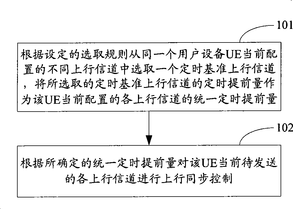
[0076] Step 102: Perform uplink synchronization control on each uplink channel currently to be transmitted by the UE according to the determined unified timing advance.

[0077] In specific implementation, for the case where the timing advance of continuous uplink DPCH or discontinuous DPCH is used as the uniform fixed advance of each channel, Node B can calculate a new timing advance according to the continuous uplink DPCH or discontinuous DPCH , and obtain the SS command...


PUM


Abstract

The invention discloses an uplink synchronization control method, a base station and a user device thereof. Wherein the method comprises: selecting a reference uplink communication channel from different uplink communication channels of one user device according to prearranged selecting principles, taking the timing initial lead of the reference uplink communication channel as the uniform timing initial lead of each uplink communication channel, carrying out uplink synchronization control to each uplink communication channel according to the uniform timing initial lead, and thereby improving the data throughput.

Description

technical field [0001] The present invention relates to mobile communication technology, in particular to an uplink synchronization control method, base station and user equipment (UE). Background technique [0002] In the technical field of mobile communication, two or more uplink channels may appear simultaneously in one uplink subframe or time slot. Taking TD-SCDMA (Time Division Synchronous Code Division Multiple Access) system as an example, these uplink channels may include: continuous or discontinuous uplink DPCH (Dedicated Physical Channel), HS-SICH (High Speed ​​HS-DSCH Shared Information Channel), scheduling And non-scheduled E-PUCH (E-DCH physical uplink channel), etc. [0003] In order to realize the synchronization of each uplink channel, the UE needs to send an uplink synchronization code in an uplink time slot for the Node B (base station) to perform uplink synchronization. Wherein, the timing advance (TA) for sending the uplink synchronization code is calcu...

Claims


Application Information

Patent Timeline
Patent Type & Authority Applications(China)
IPC IPC(8): H04B7/26H04B7/005
Inventor 常永宏赵训威白杰
Owner 北京万海云科技有限公司
Why Eureka
Try Eureka