
Pulling tool

A tool and workpiece technology, applied in the field of pulling tools, can solve the problems of low successful separation rate, influence analysis results, high labor intensity, etc., to reduce labor intensity, avoid ring damage, and improve accuracy.

Inactive Publication Date: 2010-04-14
HONG FU JIN PRECISION IND (SHENZHEN) CO LTD +1
View PDF5 Cites 0 Cited by
  • Summary
  • Abstract
  • Description
  • Claims
  • Application Information

AI Technical Summary

Problems solved by technology

Using this separation method not only has high labor intensity and low efficiency, but also because it is separated by deformation, it is easy to form destructive deformation and cause damage to the solder joints of BGA parts. The successful separation rate is low, causing misjudgment and affecting the analysis results.

Method used


Image

  • Pulling tool
  • Pulling tool
  • Pulling tool

Examples


Embodiment Construction

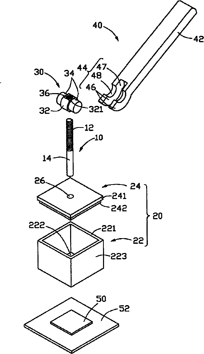
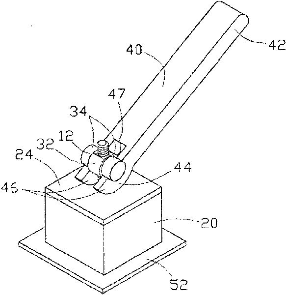
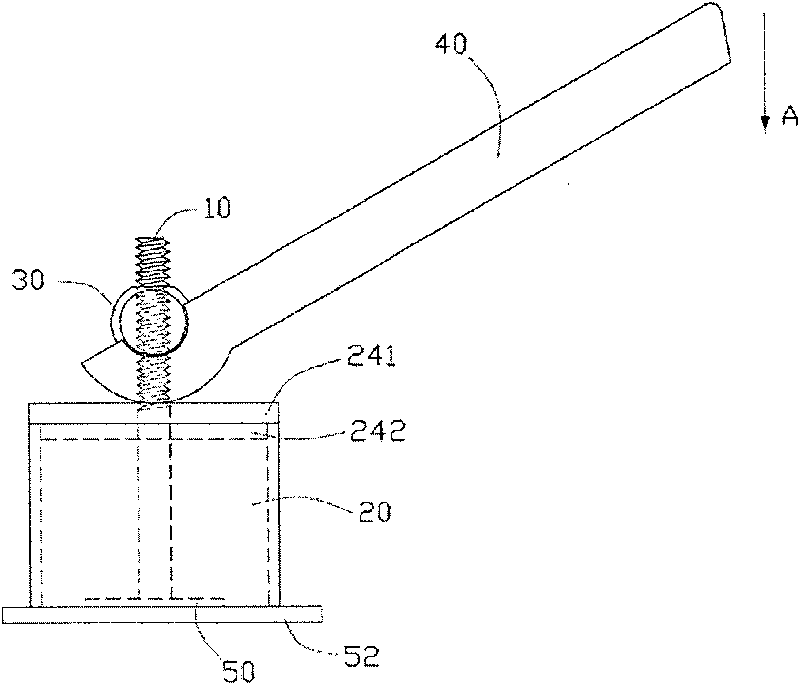
[0011] Please refer to figure 1 , the preferred embodiment of the pulling tool of the present invention is used to separate the BGA part 50 from the PCB board 52, which includes a pulling rod 10, a support seat 20 for fixing the pulling rod 10, and a The rotating shaft 30 on the pulling rod 10 and a wrench 40 engaged on the rotating shaft 30 .

[0012] The pulling rod 10 is a long round rod, one end of which is a threaded portion 12 and the other end is a free end 14 . The end face of the free end 14 is bonded to the BGA piece 50 by AB colloid and lime.

[0013] The support base 20 includes a box body 22 and a cover plate 24 covering the box body 22 . The box body 22 is a square cylinder, including four side walls 223 connected end to end and an upper edge 221 , and a cavity 222 is formed around the side walls 223 . The cover 24 includes an integrally formed covering portion 241 and a matching portion 242 extending from the bottom of the covering portion 241 . The matching...


PUM


Abstract

Disclosed is a drawing tool, comprising a support seat, a drawing rod which is threaded through the support seat and is used to adhere the work piece to be drawn upwards, a rotary shaft which is connected with the drawing rod and a wretch which is used to combine one end of the wretch with the rotary shaft clip to support the support seat. When pressing the wretch, the wretch applies force on therotary shaft so as to enable a drawing rod to draw up a work piece. The drawing tool is provided a wretch with a long bar operating part and the piece is drawn up through pressing the long bar operating part. The usage of the leverage principle of the long bar operating par reduces the labor strength sand saves the energy. Besides, the wretch and the rotary shaft of the drawing tool integrally forma shaft rotary mechanism, so as to ensure the drawing force to be constantly vertical to the piece and avoid the damage on the work piece when the drawing force is inclined.

Description

technical field [0001] The invention relates to a pulling tool, in particular to a pulling tool which is convenient for pulling and separating two welded workpieces. Background technique [0002] With the rapid development of information technology, computers, as a bridge for the transmission of information, are becoming more and more important. Ball grid array packaging (Ball Grid Array, BGA) is a packaging method for integrated circuits using an organic carrier board, and is also an important packaging method for printed circuit boards (Printed Circuit Board, PCB board). The contact between the components (BGA parts) packaged by BGA and the PCB board will directly affect the use of the computer. In general, each BGA part has several pins, and most PCB boards will assemble at least one BGA part, and some even have 10 to 20 BGA parts. Therefore, 25 to 50% of the solder joints in a complex PCB belong to BGA parts. If there is a problem with one of these solder joints, the c...

Claims


Application Information

Patent Timeline
Patent Type & Authority Patents(China)
IPC IPC(8): B25B27/14
Inventor 刘鹏
Owner HONG FU JIN PRECISION IND (SHENZHEN) CO LTD
Learn More