Regulating mechanism for working gap

A technology for working gaps and adjusting mechanisms, which is applied to power transmission devices, printing, transfer materials, etc., can solve the problems of difficult maintenance, complex structure of adjusting mechanisms, and high production costs, and achieves simplified main structure of guide shafts, which is beneficial to Use the effects of maintenance and difficulty reduction

Inactive Publication Date: 2009-03-25
FUJIAN SHIDA COMP EQUIP
View PDF0 Cites 5 Cited by
  • Summary
  • Abstract
  • Description
  • Claims
  • Application Information

AI Technical Summary

Problems solved by technology

However, the structure of the existing adjustment mechanism is complicated, the production cost is high, and the use and maintenance are difficult

Method used


Image

  • Regulating mechanism for working gap
  • Regulating mechanism for working gap
  • Regulating mechanism for working gap

Examples


Embodiment Construction

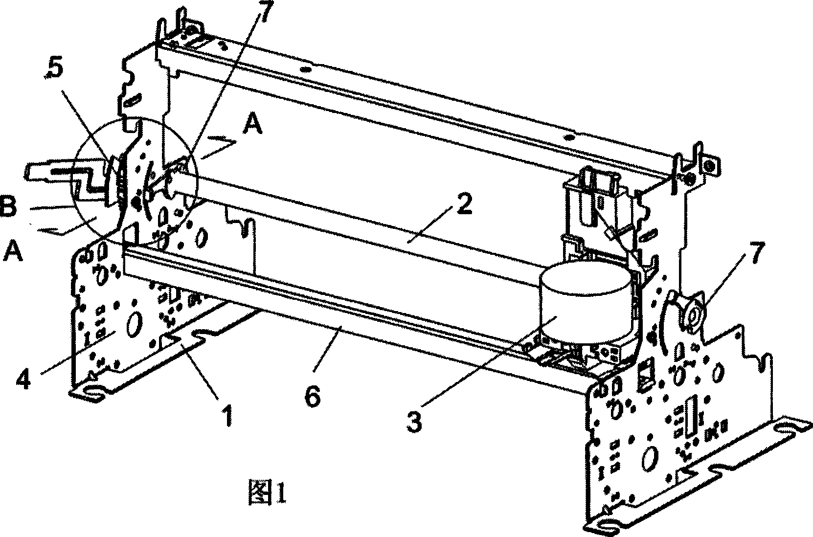
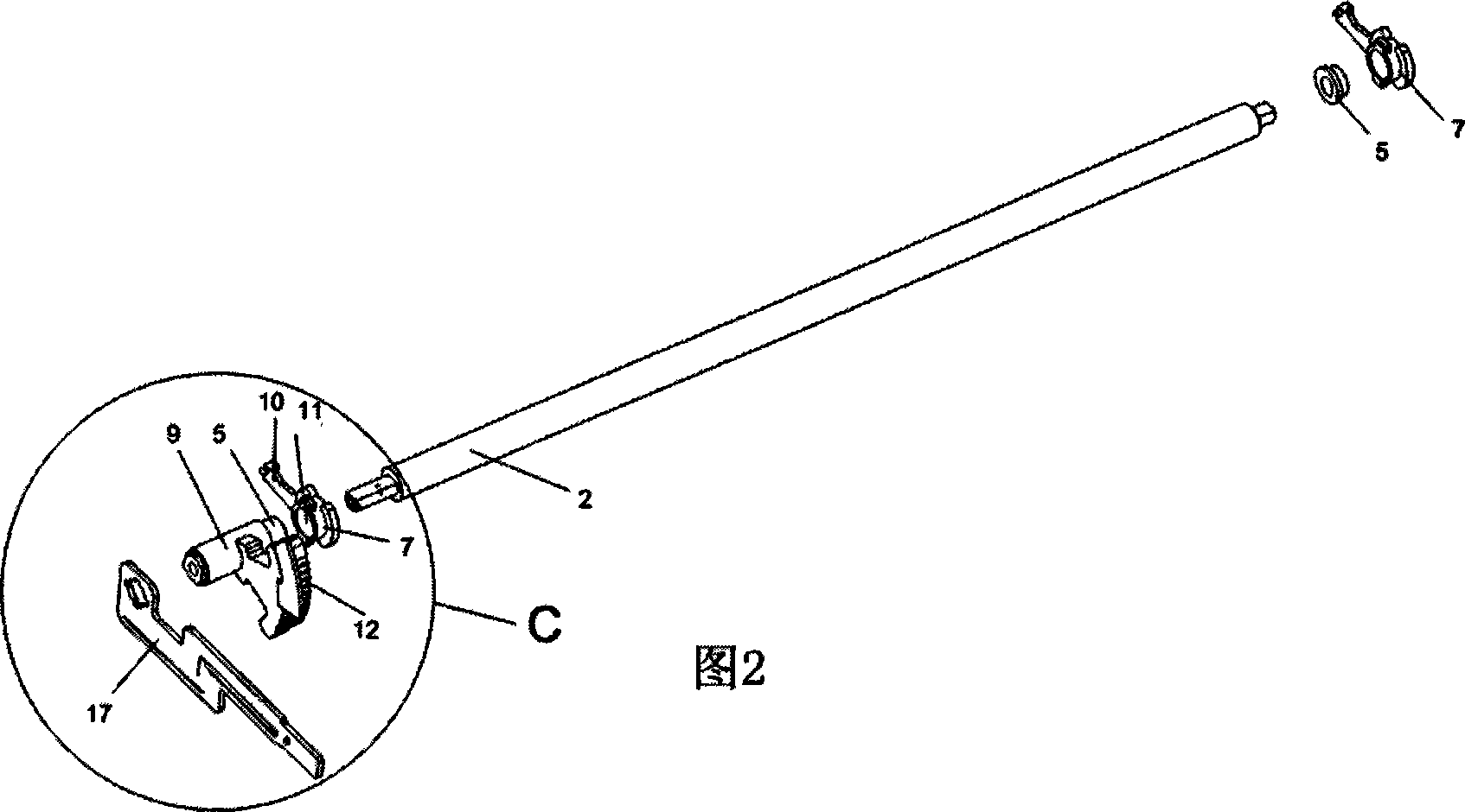
[0013] As shown in Figure 1, the present invention comprises the working end guide shaft 2 that is arranged on the frame 1 horizontally, the working end head 3 (such as printing head) that can slide laterally along the guide shaft and the support that is located at both sides of the frame The seat 4 is characterized in that a pair of eccentric circular shaft sleeves 5 are arranged on the support seats 4 on both sides and are fixedly connected to both ends of the guide shaft 2, so that the eccentric circular shaft sleeves can drive the guide shaft 2 and the working end when rotating. The head 3 (such as the printing head) is adjusted for the upper and lower gaps relative to the working plane of the frame (such as the printing plate 6).

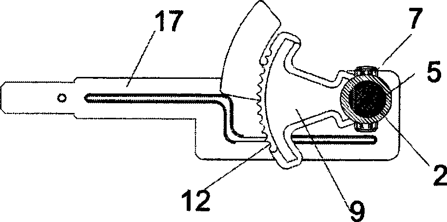
[0014] In order to realize the parallelism adjustment of the working ends, the outer circumferences of the above-mentioned pair of eccentric circular shaft sleeves 5 are respectively connected in rotation with the bearing holes 8 of the supporti...


PUM


Abstract

The invention relates to a working clearance adjusting mechanism, comprising a guide shaft which is transversely arranged on the frame, a working end which can transversely slide in the guide shaft and bearing seats which are arranged at two sides of the frame. The working clearance adjusting mechanism is characterized in that the bearing seats at two sides are provided with a pair of eccentric round shaft sleeves which are fixedly connected at two ends of the guide shaft respectively so as to lead the eccentric round shaft sleeve to drive the guide shaft and the working end to adjust the upper and lower clearance on the working plane of the frame during the rotation process of the round shaft sleeve; the device can realize the position adjustment of the working end, furthermore, the structure is simple and easy to be produced, manufactured and maintained. The working clearance adjusting mechanism has novel concept, reasonable design and considerable market application prospect.

Description

technical field [0001] The invention relates to a working gap adjusting mechanism. Background technique [0002] There are two important parameters of existing dot-type printing equipment, namely, the working gap of the working end and the parallelism relative to the frame. changes within the specified range. To be able to adapt to processed products of different specifications, and to allow the working ends to work under the designed working gap to achieve the best working effect, a mechanism that can adjust the working gap and parallelism is needed. However, the existing adjusting mechanism has complicated structure, high production cost and great difficulty in use and maintenance. Contents of the invention [0003] The purpose of the present invention is to provide a working gap adjustment mechanism, which can not only realize the position adjustment of the working end, but also has a simple structure and is easy to manufacture, use and maintain. [0004] The technic...

Claims


Application Information

Patent Timeline
Patent Type & Authority Applications(China)
IPC IPC(8): B41J25/308B41J25/316
Inventor 林艳青曾光贤陈铭邦
Owner FUJIAN SHIDA COMP EQUIP
Why Eureka
Try Eureka