Combustor for stove

A burner, burner head technology, applied in the direction of burner, gas fuel burner, combustion method, etc., can solve the problems of no practicality, difficult cleaning, etc.

Inactive Publication Date: 2012-09-05
RINNAI CORP
View PDF1 Cites 0 Cited by
  • Summary
  • Abstract
  • Description
  • Claims
  • Application Information

AI Technical Summary

Problems solved by technology

However, this is impractical because cleaning becomes difficult in the case where the upper flame port is clogged with boiled spillage

Method used


Image

  • Combustor for stove
  • Combustor for stove
  • Combustor for stove

Examples


Embodiment Construction

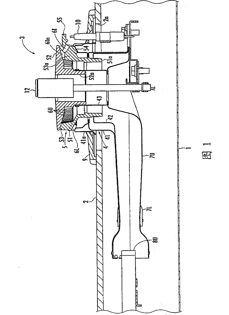
[0027] refer to figure 1 , 1 denotes a stove main body, 2 denotes a panel covering the upper surface of the stove main body 1, and 3 denotes a burner for a stove. In the panel 2, the opening 2a for burners is opened. In addition, on the panel 2, a bracket (not shown in the figure) is placed so as to surround the burner opening 2a. Furthermore, the cooking vessel placed on the stand is heated by the burner 3 .

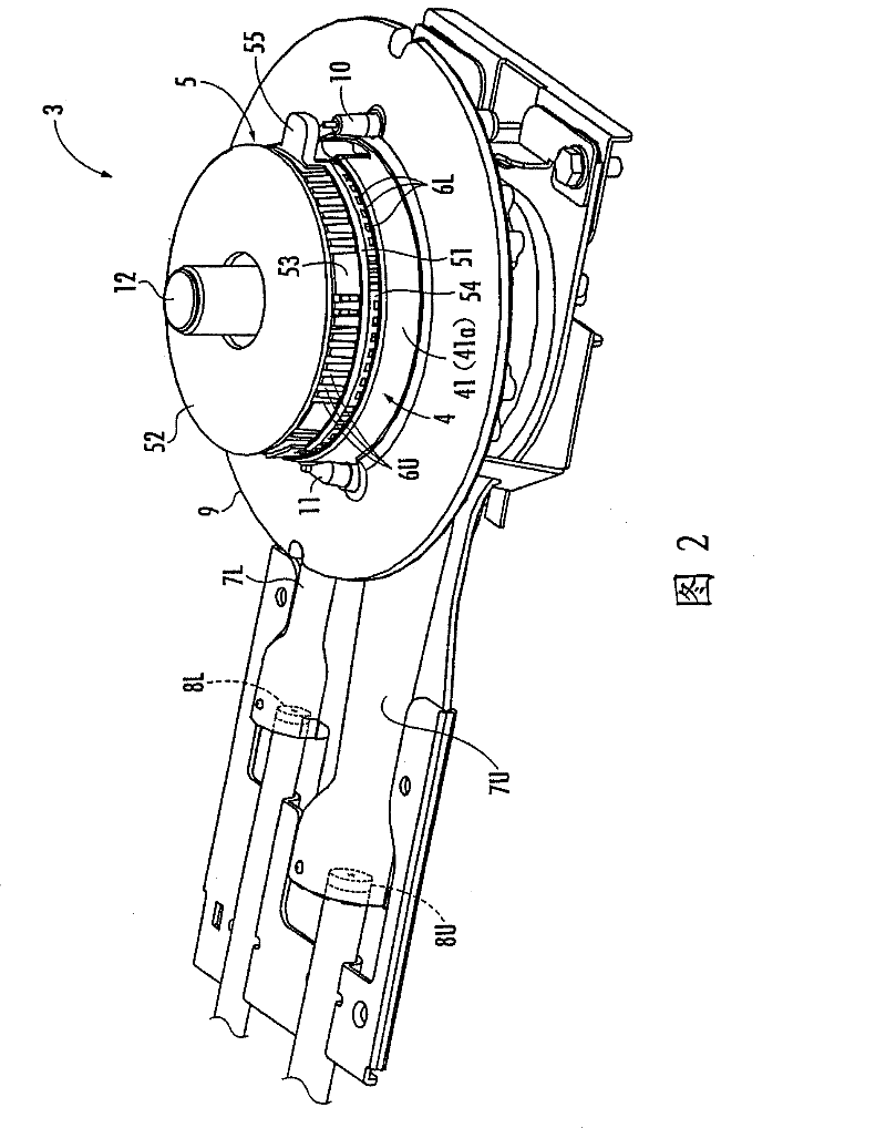
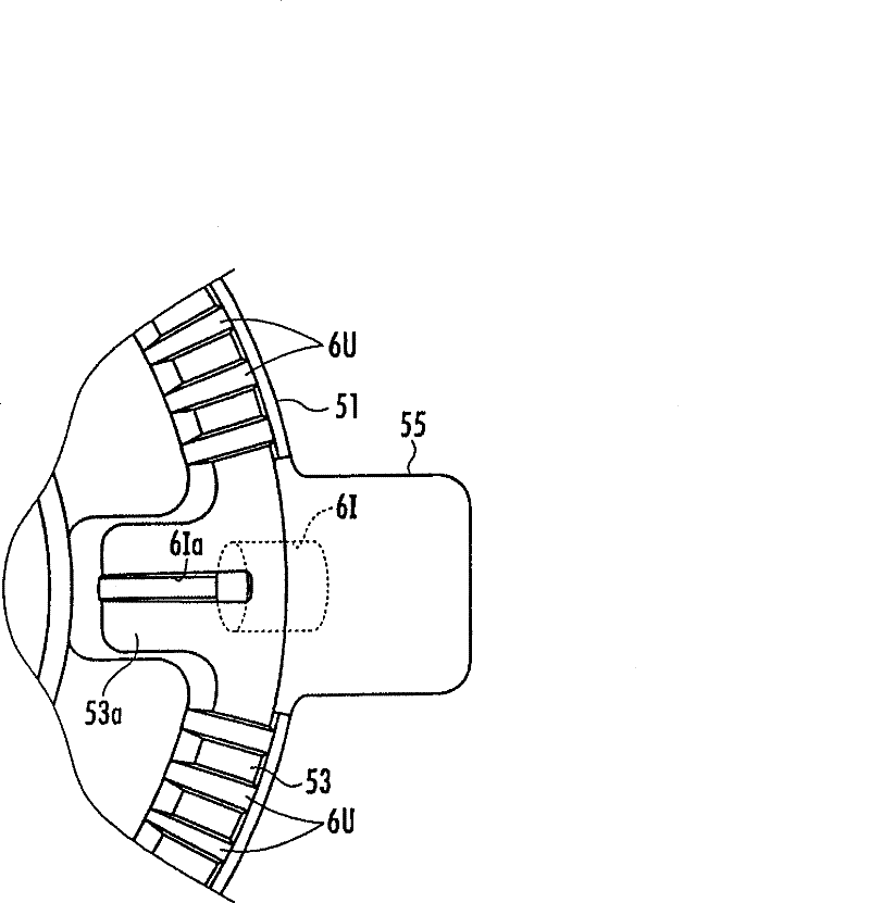
[0028] The burner 3 has a burner body 4 and a burner head 5 on the burner body 4 , wherein the burner body 4 passes through the burner opening 2 a. On the circumferential surface of the burner head 5, such as figure 2 As shown, there are a plurality of flame ports 6U, 6L in the upper and lower layers, and an ignition flame port 6I is opened in one of the circumferential directions. There is a gap on it. Here, the upper layer flame port 6U is not provided at multiple positions corresponding to the bracket claws of the bracket in the circumferential direction, so as...


PUM


Abstract

A burner for a cooking stove comprises an upper layer flame hole, a lower layer flame hole, and an ignition flame hole, the upper and the lower layer flame holes are placed on a circumferential surface of a burner head formed of a lower head component and an upper head component, wherein the lower layer flame hole is determined between the lower head component and a burner main body, the upper layer flame hole is determined between the upper head component and the lower head component. Therefore, the burner is not ignited in the case of forgetting to set the upper head component, which can prevent backfire or poor burning because the flame transfers to the mixed gas for the upper layer flame hole. The solution is that: an objective part opposite to a spark plug is arranged on one of the lower head component and the upper head component; the ignition flame hole, which is placed in the circumferential surface of the lower head component and on the lower side of the objective part, communicates the space between the lower head component and the upper head component; furthermore, the ignition flame hole is formed in a way of facing toward the circumferential surface of the lower head component and inclining downward.

Description

technical field [0001] The invention relates to a burner for a stove with upper and lower layers of flame ports, wherein the upper and lower layers of flame ports are opened at the circumferential surface of the burner head, and the burner head is installed on the burner main body. Background technique [0002] In the past, as such a burner for a stove, there is known a burner in which the burner head is composed of two members, a lower head member and an upper head member, and the burner main body and the lower head A lower flame port is defined between the components, and an upper flame port is defined between the lower head member and the upper head member (for example, refer to Patent Document 1). In addition, in this burner for a stove, one of the lower flame ports is used as an ignition flame port ignited by a spark plug, and by igniting the ignition flame port, the other lower layer flame ports and the upper layer flame port are transferred and ignited. . [0003] H...

Claims


Application Information

Patent Timeline
Patent Type & Authority Patents(China)
IPC IPC(8): F23D14/02F23D14/46
CPCF23D14/06F23D14/58F24C3/027F24C3/085F24C3/10
Inventor 赤木万之
Owner RINNAI CORP
Why Eureka
Try Eureka