

Shift device
A technology of shifting device and shifting fork, which is applied to mechanical control device, transmission control, element with teeth, etc., can solve the problems such as twisting and longitudinal bending of shifting fork shaft, and saves the position, simplicity and cost. , the effect of cheap manufacturing
- Summary
- Abstract
- Description
- Claims
- Application Information
AI Technical Summary
Problems solved by technology
Method used
Image

Examples
Embodiment Construction
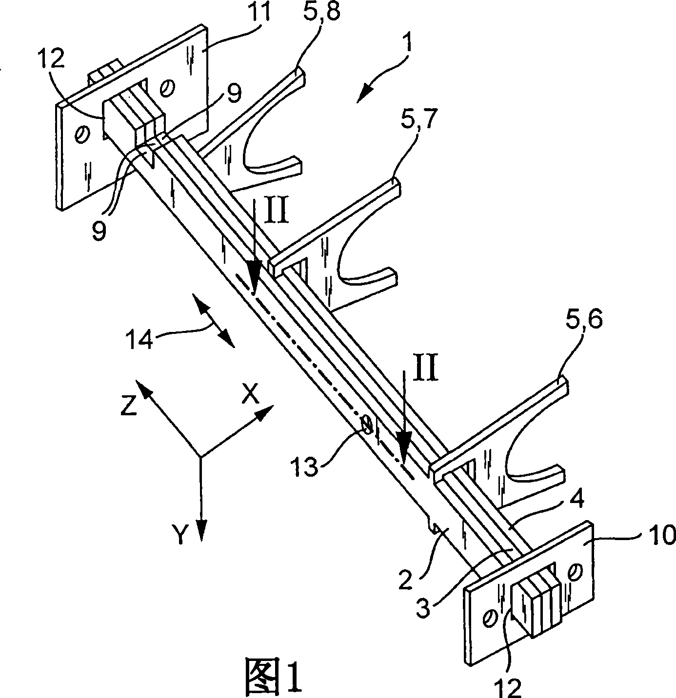
[0021] FIG. 1 shows a diagram of a shifting device 1 with a bundle of shift fork shafts 2 , 3 and 4 . Each shift fork shaft 2 , 3 , 4 has one of the shift forks 6 , 7 or 8 and a shift opening 9 as actuating part 5 . The shift fork shafts 2 , 3 , 4 are mounted longitudinally displaceably in the bearing end shields 10 and 11 by means of bearings 12 , not described in detail, in a parallel Z longitudinal direction indicated by double arrow 14 .
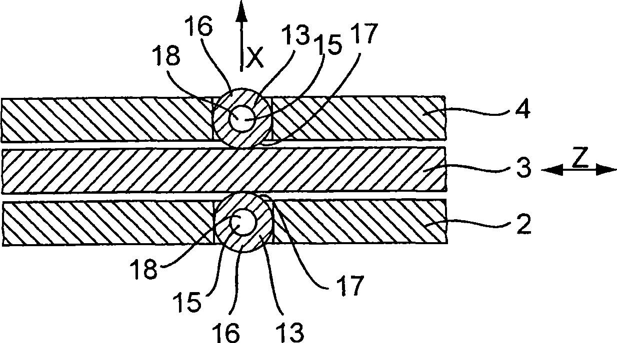
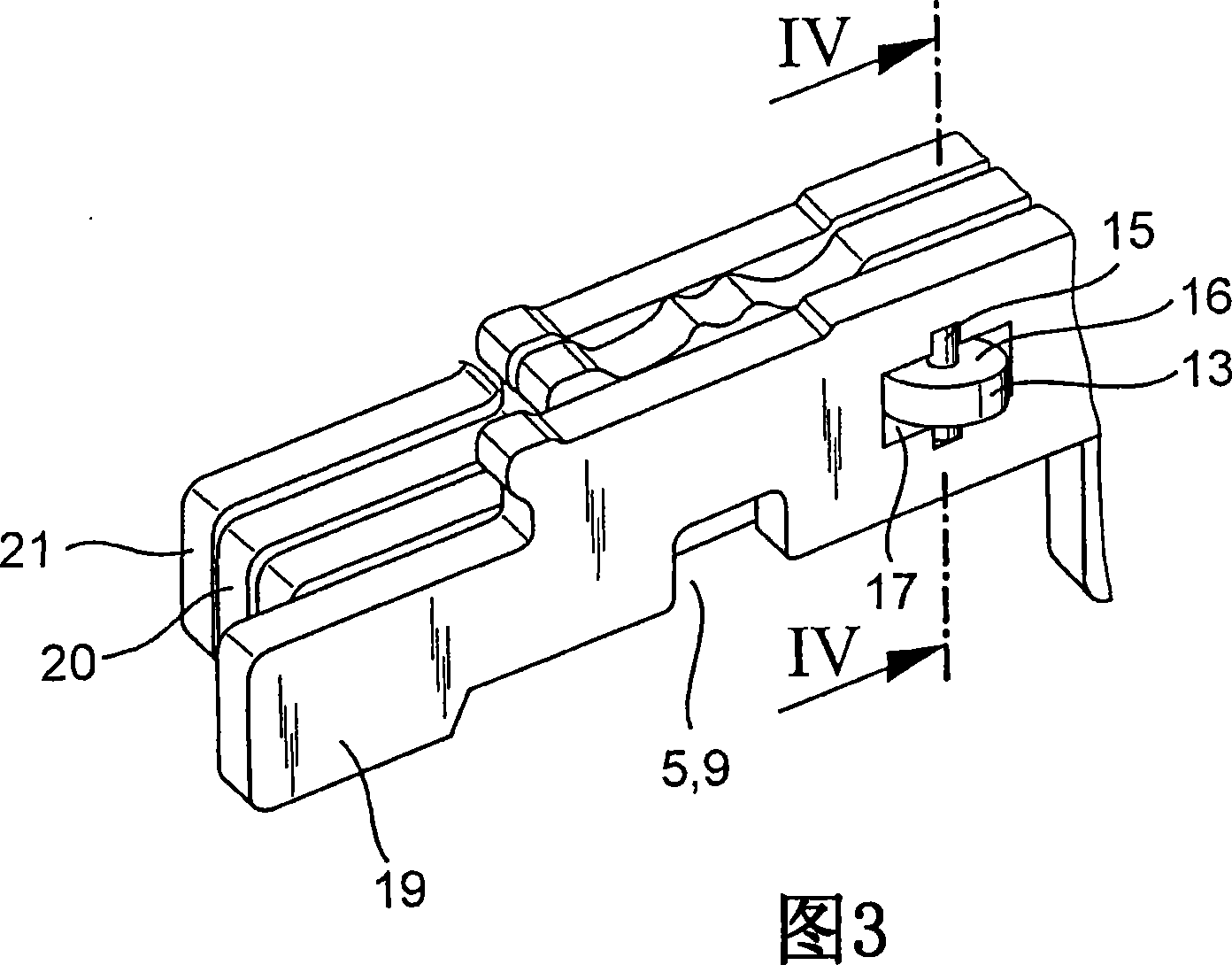
[0022] The shift fork shafts 2 and 4 also each have at least one roller bearing 13 . Roller bearings 13 in figure 2 are shown in section and each consist of a pin 15 and a roller 16 . The pin 15 is held stationary in a receptacle 17 of the respective shift fork shaft 2 or 4 and serves as a shaft for a roller 16 which is rotatably mounted on the pin 15 . The roller 16 is rotatably sliding or rolling mounted on the pin 15 about the longitudinal center axis 18 . It is also conceivable to mount a plurality of rollers on pins instead of o...
PUM
 Abstract
Description
Claims
Application Information