
Speed reducer for blade electric vehicle

A pure electric vehicle and reducer technology, which is applied in the direction of vehicle gearboxes, transmission boxes, transmission components, etc., can solve the problems of not being able to output low-speed high-torque, etc., and achieve the effect of large carrying capacity, no sense of frustration, and low noise

Inactive Publication Date: 2015-11-11
无锡市神力齿轮冷挤有限公司
View PDF9 Cites 0 Cited by
  • Summary
  • Abstract
  • Description
  • Claims
  • Application Information

AI Technical Summary

Problems solved by technology

The pure electric vehicle market needs a low-speed and high-torque reducer that can output low-speed and high-torque when running under starting and climbing conditions. The reducers currently on the market mainly use motor speed regulation and fixed gears to change speeds and cannot output low-speed and high-torque.

Method used


Image

  • Speed reducer for blade electric vehicle

Examples


Embodiment Construction

[0018] The present invention will be further described below in conjunction with specific drawings and embodiments.

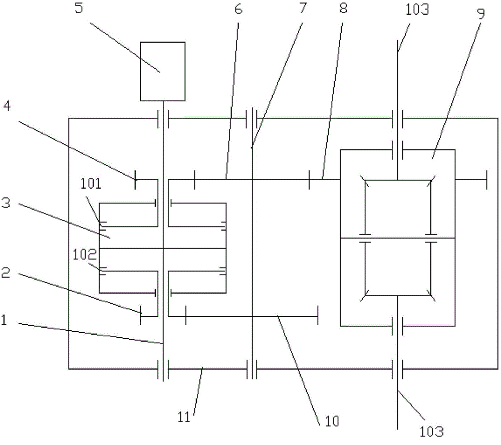
[0019] The reducer for pure electric vehicles provided by the present invention is such as figure 1 Shown, including: input shaft 1, second speed input gear 2, clutch 3, first speed input gear 4, middle first speed gear 6, middle shaft 7, differential transmission gear 8, differential 9, middle second speed gear 10 and shell 11; wherein the shell 11 uses an aluminum alloy shell. The reducer is connected to the motor 5.

[0020] The outer circle of one end of the input shaft 1 is rotatably connected with the housing 11 and connected to the motor 5 in series through the housing 11. The first gear input gear 4, the clutch 3 and the second gear input gear 2 are respectively arranged in the middle of the input shaft 1, and the outer circle of the other end rotates with the housing 11 Connection; the inner hole of the first gear input gear 4 rotates with the input shaft...


PUM


Abstract

The invention provides a speed reducer for a blade electric vehicle. The speed reducer comprises an input shaft, a two-gear input gear, a clutch, a one-gear input gear, a middle one-gear gear, an intermediate shaft, a differential drive gear, a differential mechanism, an intermediate two-gear gear and a shell. The clutch and the two-gear input gear are added at one end of the input shaft. The fixed speed changing is changed into two-gear speed changing, the transmission ratios are 1:17 and 1:8, and the large torque is output through the large transmission ratio of 1:17 under the work conditions of starting and climbing. The power is output through the ratio of 1:8 during driving, it is guaranteed that gear shifting can be carried out without cutting off power transmission during driving, the gear shifting comfort level is high, and jerking feeling is avoided. The transmission gears are all designed into helical gears, and carbonitriding thermal processing and surface gear grinding machining are carried out on the helical gears; and the contact ratio of gear meshing is large, noise is low during running, and the bearing capability is large. The differential mechanism is designed at the output end, and the requirement for the speed difference of wheels on the two sides of the vehicle during turning can be met.

Description

Technical field [0001] The invention relates to a reducer for automobiles, in particular to a reducer for pure electric automobiles. Background technique [0002] With the implementation of my country's new energy policy, pure electric vehicles have received more and more attention, and the country has recently introduced a number of incentive measures to further promote the development of pure electric vehicle technology. The pure electric vehicle market needs a low-speed and high-torque reducer when running under starting and climbing conditions. At present, the reducer involved in the market is mainly through motor speed regulation and fixed gear transmission that cannot output low-speed high torque. Summary of the invention [0003] The purpose of the present invention is to overcome the deficiencies in the prior art, and provide a reducer for pure electric vehicles that can output low speed and large torque when running under starting and climbing conditions, with large carry...

Claims


Application Information

Patent Timeline
Patent Type & Authority Applications(China)
IPC IPC(8): F16H3/091F16H57/02F16H57/023F16H55/06F16H55/17
CPCF16H3/091F16H55/06F16H55/17F16H57/02F16H57/023F16H2200/0021
Inventor 王维涛王建江
Owner 无锡市神力齿轮冷挤有限公司
Learn More