Supercharge Your Innovation With Domain-Expert AI Agents!

Battery charger

A technology for battery chargers and batteries, which is applied in battery circuit devices, current collectors, safety/protection battery circuits, etc., and can solve the problems that battery packs cannot be used

Inactive Publication Date: 2013-01-02
KOKI HLDG CO LTD
View PDF1 Cites 0 Cited by
  • Summary
  • Abstract
  • Description
  • Claims
  • Application Information

AI Technical Summary

Problems solved by technology

However, since the current capacity in general power tools is predetermined, it is not possible to use battery packs with different values ​​of current capacity depending on the way of operation.

Method used


Image

  • Battery charger
  • Battery charger
  • Battery charger

Examples


Embodiment Construction

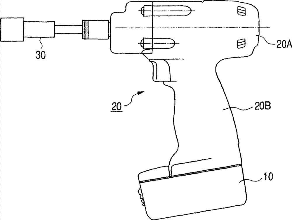
[0064] Before describing the battery charger according to the present invention, a battery device and an electric tool using the battery device will be described below.

[0065] (1) Structure of the battery device

[0066] (1.1) Circuit structure

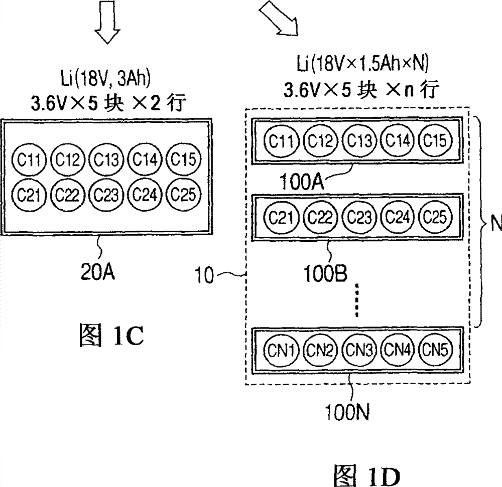
[0067] Hereinafter, a description will be given of a battery unit formed with a battery pack charged by the battery charger of the present invention. FIG. 3 shows a block circuit diagram in which battery assemblies 100A and 100B are connected in parallel with each other. Since the circuit of the battery pack 100A is the same as that of the battery pack 100B, only the battery pack 100A will be described.

[0068] In this embodiment, battery pack 100A includes five lithium batteries C11-C15 connected in series. These cells C11-C15 are generally referred to as battery pack C10.

[0069] The anode terminal of the battery pack C10 is connected to the discharge anode terminal DC, and the cathode terminal of the battery pack C10 is con...


PUM


Abstract

A battery charger includes an accommodating part for accommodating a group of cells and a plurality of cell assemblies respectively having charging terminals for charging the group of cells; a first terminal plate formed in the surface of the accommodating part to come into contact with the charging terminal of the first cell assembly and a second terminal plate coming into contact with the second cell assembly; a switching element for interrupting voltage from an ac power source; a unit for rectifying and smoothing the voltage interrupted by the switching element; and a unit for applying the smoothed dc voltage respectively to the first and second terminal plates.

Description

technical field [0001] The present invention relates to a battery charger for charging a battery device using Stackable Cell Assembly Technology (Stackable Cell Assembly Technology, hereinafter abbreviated as SCAT). Background technique [0002] Initially, referring to Figure 1A - 1D, describe the SCAT concept proposed by the inventor of the present invention. [0003] Cordless power tools 20 such as electric drivers, electric drills, and impact tools have motors to generate rotational power, and are designed to reduce the rotational speed of the motor through a reduction mechanism, and then transmit the rotational power to the tip tool. [0004] exist Figure 1A In , reference numeral 20 denotes a cordless electric tool. The cordless power tool includes a main body part 20A and a handle part 20B. A tool head 30 is attached to the end of the body part 20A. One end of the handle part 20B is connected to the main body part 20A, and the battery device 10 is attached to the ...

Claims


Application Information

Patent Timeline
Patent Type & Authority Patents(China)
IPC IPC(8): H02J7/00H02J7/02
CPCH02J7/0026H02J7/0014H02J7/00308H02J7/00304
Inventor 船桥一彦大森和博塙浩之渡部伸二
Owner KOKI HLDG CO LTD
Features
  • R&D
  • Intellectual Property
  • Life Sciences
  • Materials
  • Tech Scout
  • Unparalleled Data Quality
  • Higher Quality Content
  • 60% Fewer Hallucinations
Learn More