A MEMS resonator, a method of manufacturing thereof, and a MEMS oscillator

A technology of resonators and oscillators, applied in the direction of electrical components, impedance networks, etc., can solve problems such as the difficulty of manufacturing MEMS resonators, and achieve the effect of reducing the effective interval width

Inactive Publication Date: 2011-06-29
NXP BV
View PDF2 Cites 0 Cited by
  • Summary
  • Abstract
  • Description
  • Claims
  • Application Information

AI Technical Summary

Problems solved by technology

[0005] The disadvantage of known MEMS resonators is that it is difficult to manufacture

Method used


Image

  • A MEMS resonator, a method of manufacturing thereof, and a MEMS oscillator
  • A MEMS resonator, a method of manufacturing thereof, and a MEMS oscillator
  • A MEMS resonator, a method of manufacturing thereof, and a MEMS oscillator

Examples


Embodiment Construction

[0037]The present invention will be described in terms of particular embodiments with reference to certain drawings but the invention is not limited thereto, its scope being limited only by the appended claims. Any reference signs in the claims should not be construed as limiting the scope. The drawings described are only schematic and non-limiting. In the drawings, the size of some of the elements is exaggerated and not drawn on scale for illustrative purposes. Where the terms "comprising" or "comprises" are used in the present description and claims, other elements or steps are not excluded. Where a singular noun is referred to (eg "a" or "an", "the"), where an indefinite or definite article is used, this includes a plural of such noun unless expressly stated otherwise.

[0038] Moreover, in the description and claims, the terms first, second, third, etc. are used to distinguish similar elements, not to describe sequential and chronological order. It is to be understood t...


PUM


Abstract

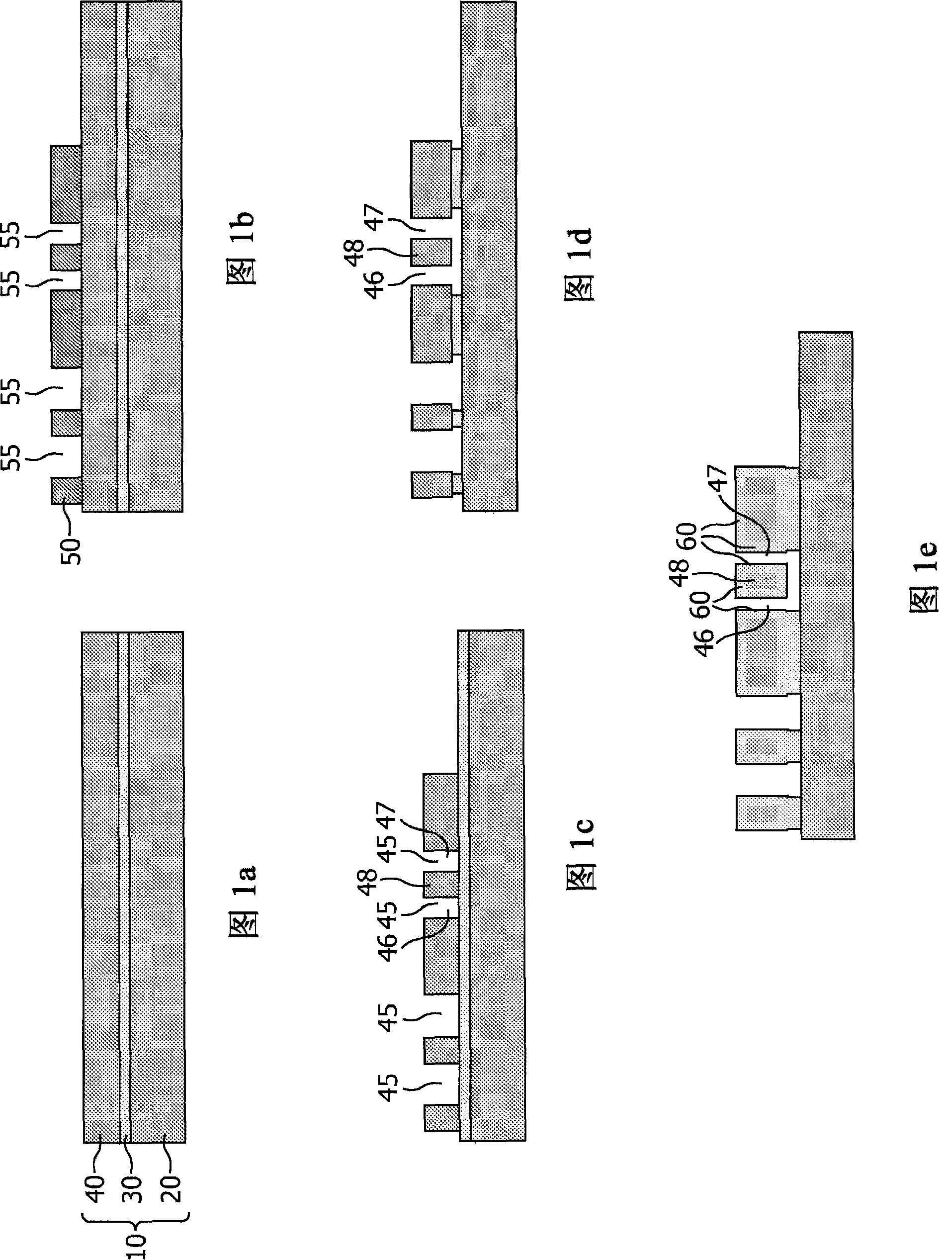
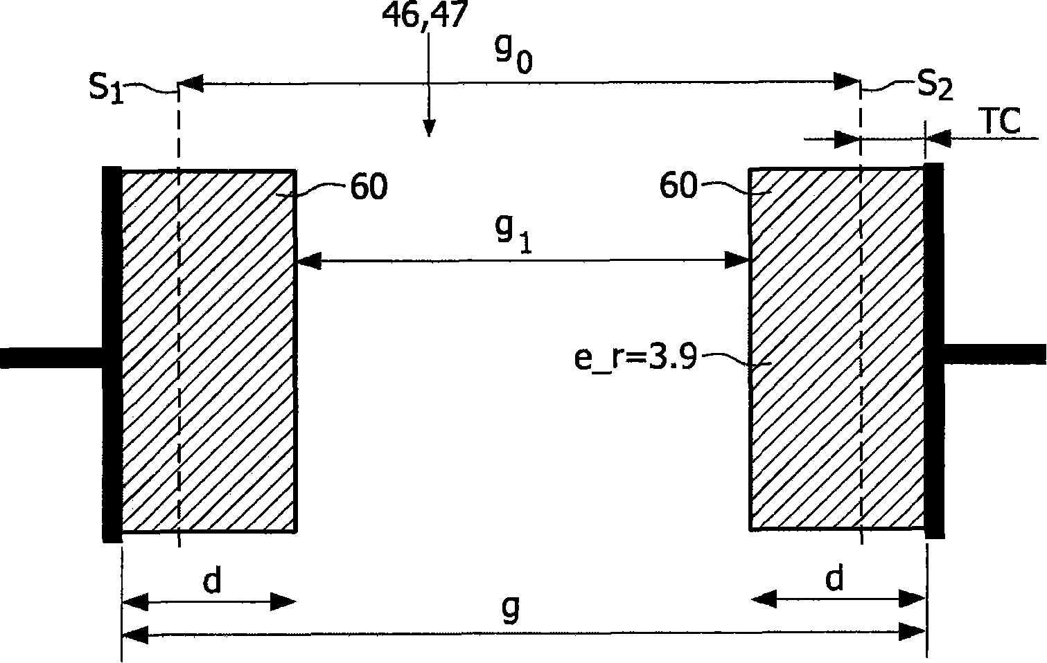
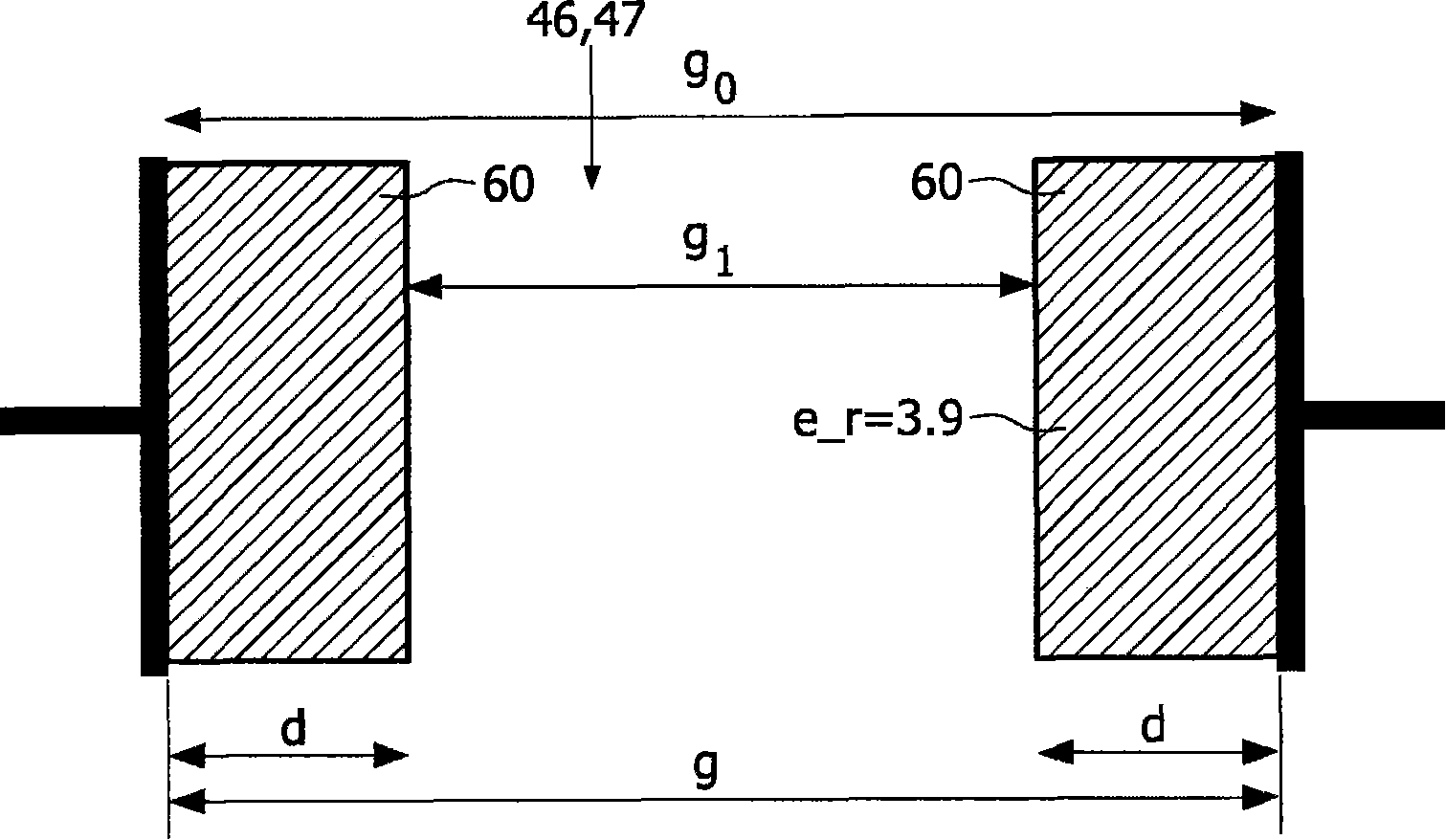
The invention relates to a MEMS resonator comprising a first electrode, a movable element (48) comprising a second electrode, the movable element (48) at least being movable towards the first electrode, the first electrode and the movable element (48) being separated by a gap (46, 47) having sidewalls. According to the invention, the MEMS resonator is characterized in that the gap (46, 47) has been provided with a dielectric layer (60) on at least one of the sidewalls.

Description

technical field [0001] The invention relates to a MEMS resonator comprising a first electrode and a movable element comprising a second electrode, the movable element being movable at least towards the first electrode, the first electrode and the movable element being spaced by a side wall separate. [0002] The invention also relates to a method of manufacturing such a MEMS resonator. [0003] The invention also relates to a MEMS oscillator comprising a MEMS resonator, and to an integrated circuit comprising such a MEMS oscillator. Background technique [0004] A MEMS resonator is known from WO 2004 / 027796 A2. This document discloses a planar beam resonator with fixed supports at both ends. The two-terminal clamped beam resonator includes a single crystal silicon (SCS) beam arranged between two clamped regions. The SCS beam has a defined width and height and is used as the resonating element of the clamped beam resonator 200 . The drive and sense electrodes face each o...

Claims


Application Information

Patent Timeline
Patent Type & Authority Patents(China)
IPC IPC(8): H03H9/02H03H3/007
CPCH03H9/02244H03H3/0072H03H2009/02496
Inventor 约瑟夫・T・M・范贝克巴尔特・范费尔岑
Owner NXP BV
Why Eureka
Try Eureka