Corner coupling resonator array

Active Publication Date: 2018-06-28
MURATA MFG CO LTD
View PDF6 Cites 6 Cited by
  • Summary
  • Abstract
  • Description
  • Claims
  • Application Information

AI Technical Summary

Benefits of technology

[0019]Accordingly, the MEMS resonator array disclosed herein provides reduced motional impedance at h

Problems solved by technology

However, one limitation for quartz resonators is that they are difficult to design in smaller sizes.
However, reducing the size of such resonators also results in higher electrical impedance, which is undesirable.
However, for this design, due to electrostatic actuation and out-of-plane bending mode, the resonator array 1 is not satisfactory for frequencies higher than 20 MHz as the motional impedance would still be unacceptably high for most device implementations.
The design disclosed in Non-Patent Document 2 also includes technical limitations as electrostatic actuation makes the motional impedance unacceptably high.
Moreover, vibration of the coupling beams leads to many spurious resonances in

Method used


Image

  • Corner coupling resonator array
  • Corner coupling resonator array
  • Corner coupling resonator array

Examples


Example

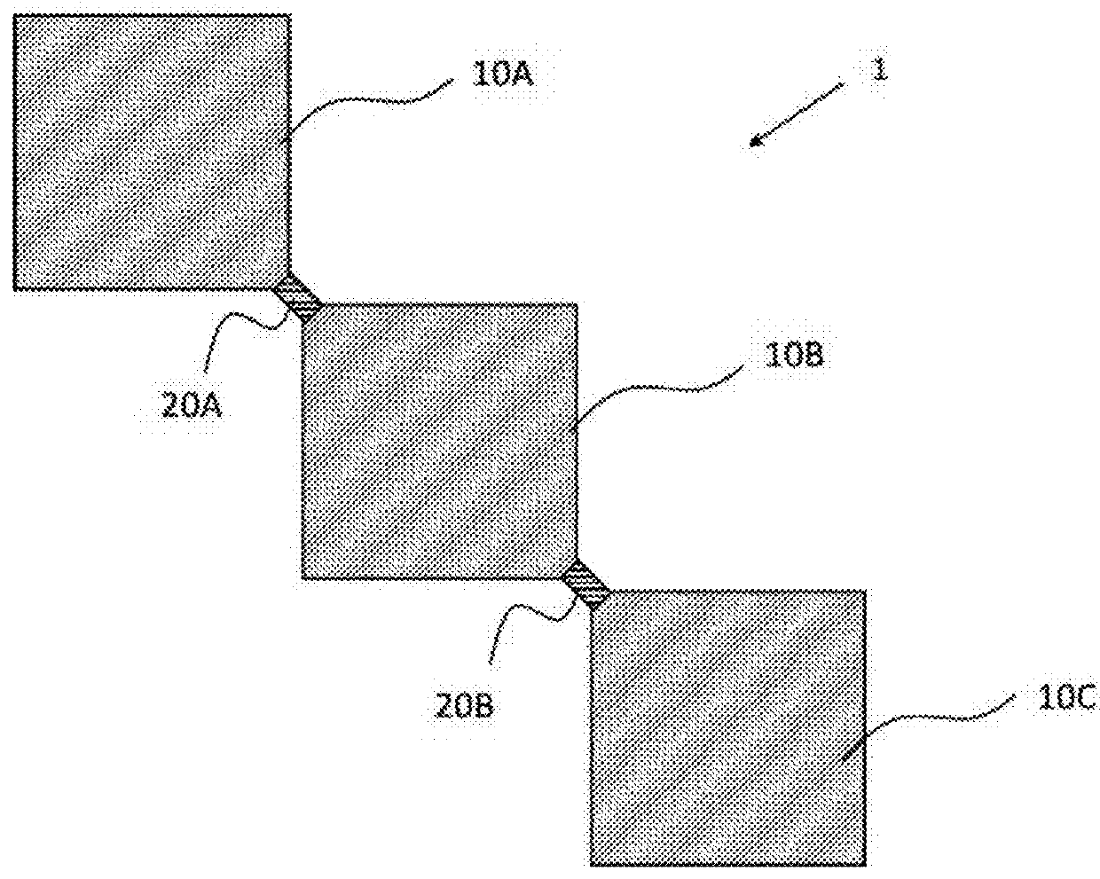
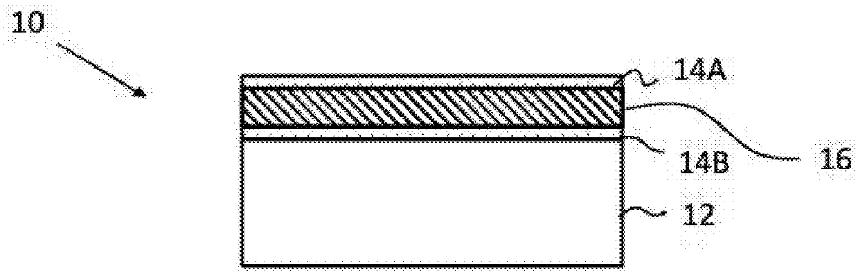
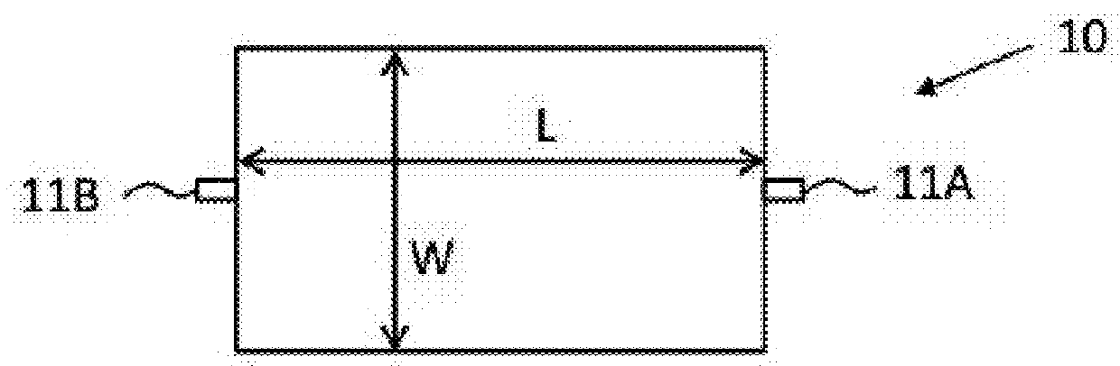
[0044]According to the exemplary embodiments described herein, MEMS resonator designs are provided to improve electrical characteristics by minimizing high motional impedance and drive level dependency that are observed in conventional MEMS designs in high frequency applications. In particular, the exemplary resonator arrays include a plurality of piezoelectric resonators that physically connect to each other for mechanical coupling as will be discussed in detail below.

[0045]Those of ordinary skill in the art will realize that the following description is illustrative only and is not intended to be in any way limiting. Other aspects will readily suggest themselves to those skilled in the art having the benefit of this disclosure. Reference will now be made in detail to implementations of the example aspects as illustrated in the accompanying drawings. The same reference indicators will be used to the extent possible throughout the drawings and the following description to refer to t...


PUM


Abstract

A MEMS resonator array is provided with improved electrical characteristics and reduced motional impedance at high frequency applications. The MEMS resonator array includes a pair of first piezoelectric resonators that are opposed to each other with a space defined therebetween. Moreover, the MEMS resonator array includes a pair of second piezoelectric resonators that are opposed to each other and that are each coupled to respective corners of each of the first piezoelectric resonators. As such, each of the second piezoelectric resonators is partially disposed in the space defined between the pair of first piezoelectric resonators.

Description

FIELD OF THE INVENTION[0001]The present invention relates generally to MEMS resonator arrays, and, more particularly, to MEMS resonator arrays with corner coupling to minimize motional impedance in high frequency applications.BACKGROUND OF THE INVENTION[0002]Microelectromechanical system (“MEMS”) resonators are small electromechanical structures that vibrate at high frequencies and are often used for timing references, signal filtering, mass sensing, biological sensing, motion sensing, and other applications. MEMS resonators are considered a common alternative to quartz timing devices to provide an accurate time or frequency reference. In general, quartz resonators have a high quality factor and piezoelectric coupling. High quality factor indicates a low rate of energy loss relative to the stored energy of the resonator, i.e., the oscillations die out more slowly. However, one limitation for quartz resonators is that they are difficult to design in smaller sizes.[0003]Accordingly, M...

Claims


Application Information

Patent Timeline
IPC IPC(8): H03H9/02H03H9/205
CPCH03H9/02433H03H2009/155H03H9/205H03H9/505H03H2009/02496H03H2009/2442
Inventor KAAJAKARI, VILLE
Owner MURATA MFG CO LTD
Why Eureka
Try Eureka