Improved unwinding coiler

A technology of uncoiler and machine base, which is applied in the field of cold roll forming machine equipment, and can solve problems such as slow unwinding and rewinding

Inactive Publication Date: 2009-04-01
肖荣
View PDF0 Cites 2 Cited by
  • Summary
  • Abstract
  • Description
  • Claims
  • Application Information

AI Technical Summary

Problems solved by technology

The disadvantage of this uncoiler is that it has no unwinding power itself, and the unwinding is realized by the traction of the subsequent processing equipment on the plat

Method used


Image

  • Improved unwinding coiler

Examples


Embodiment Construction

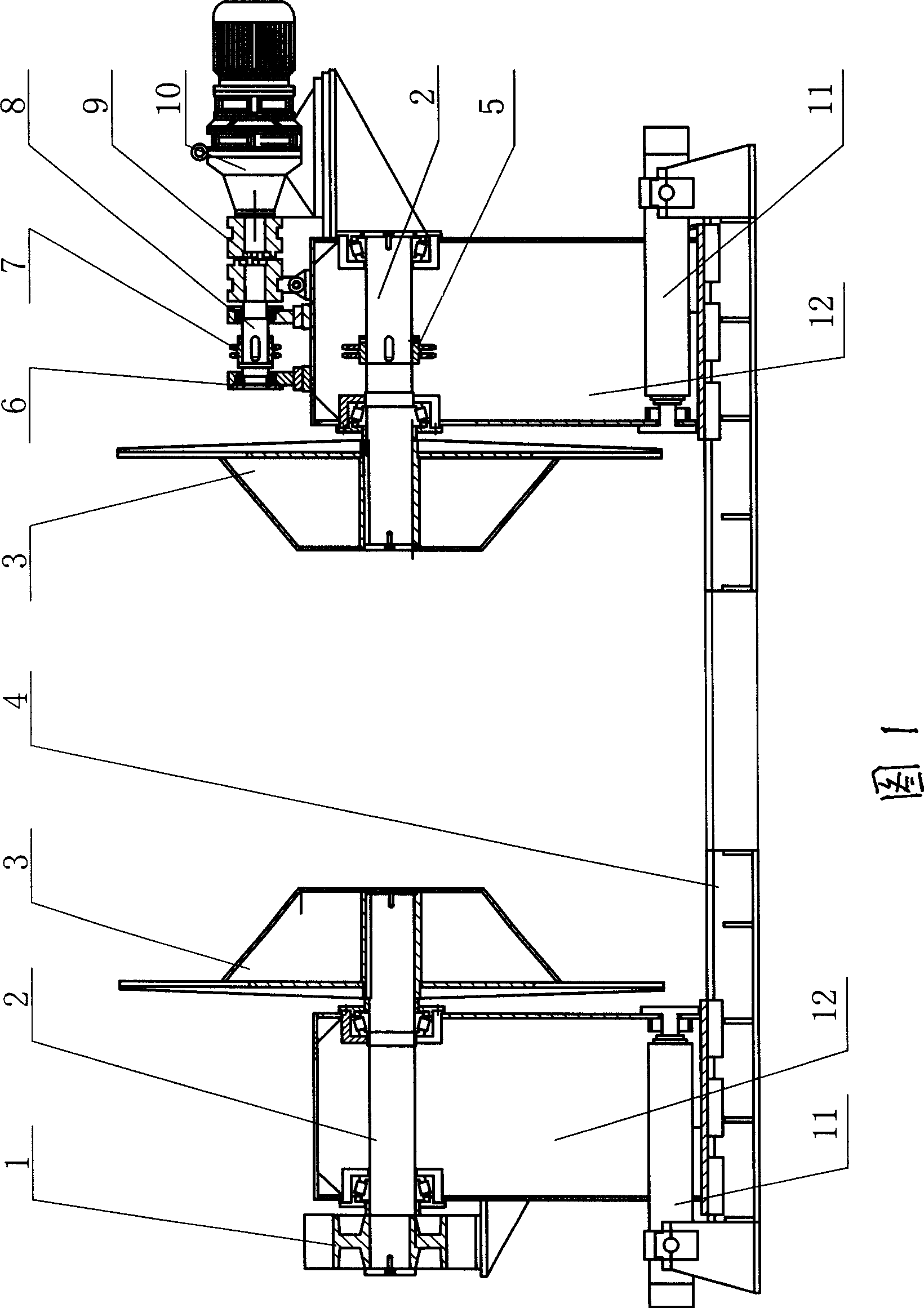
[0008] See Fig. 1, the present invention comprises machine base 4, and screw mandrel 11 is installed respectively at the two ends of machine base 4, and screw mandrel 11 on both sides is connected with support 12 of corresponding side respectively, and support 12 connects conical frame 3 by rotating shaft 2 respectively, The support 12 on one side is equipped with the motor drive structure of the rotating shaft. The motor drive structure includes a motor 10 and a driving shaft 8, the motor 10 and the driving shaft 8 are installed on a bracket 12, and 6 is a bearing seat, the motor 10 is connected to the driving shaft 8 through a clutch 9, and the driving shaft 8 is connected to the rotating shaft through the pulleys 5, 7 and a belt 2 and 1 are positioning discs.

[0009] Describe the working process of the present invention below in conjunction with accompanying drawing: during discharging, motor 10 drives driving shaft 8 by clutch 9, and driving shaft 8 drives rotating shaft ...


PUM


Abstract

The invention is an improved uncoiler. The uncoiler has sufficient power and is suitable for discharging of plates with various models. The uncoiler comprises a base and both ends of the base are respectively provided with screw rods; the screw rods are respectively connected with brackets at corresponding side and the brackets are respectively connected with a tapered rack by a rotating shaft; the uncoiler is characterized in that the bracket at one side is provided with a motor drive structure of the rotating shaft.

Description

(1) Technical field [0001] The invention relates to the technical field of cold roll forming unit equipment, in particular to an improved uncoiler. (2) Background technology [0002] Its structure of existing uncoiler comprises machine base, and the two ends of described machine base are respectively equipped with screw mandrel, and the screw mandrels on both sides are respectively connected with support, and described support is respectively connected with conical frame through rotating shaft. By adjusting the brackets on both sides, the unwinding rack with strip steel is placed between the tapered racks on both sides. The disadvantage of this uncoiler is that it has no unwinding power itself, and the unwinding is realized by the traction of the subsequent processing equipment on the plate. In this way, for large plates, it is easy to cause slow unwinding or even rewinding due to insufficient power, which cannot be matched with subsequent processing. match. (3) Contents ...

Claims


Application Information

Patent Timeline
IPC IPC(8): B21C47/16
Inventor 肖荣
Owner 肖荣
Why Eureka
Try Eureka