
Suspension structure of engine

A technology for engine mounts and engines, which is applied in the direction of power plants, jet propulsion devices, internal combustion propulsion devices, etc., can solve the problems of uneconomical, complicated vibration reduction structure of the secondary mount, and large space occupation, so as to reduce manufacturing difficulty and The effect of manufacturing cost, meeting NVH performance requirements, and saving layout space

Inactive Publication Date: 2009-04-01
CHONGQING CHANGAN AUTOMOBILE CO LTD
View PDF0 Cites 17 Cited by
  • Summary
  • Abstract
  • Description
  • Claims
  • Application Information

AI Technical Summary

Problems solved by technology

The above-mentioned two-stage suspension damping structure is complex, difficult to arrange, and takes up a lot of space. An extra sub-frame with a complex shape will cost a lot and is extremely uneconomical

Method used


Image

  • Suspension structure of engine
  • Suspension structure of engine
  • Suspension structure of engine

Examples


Embodiment Construction

[0014] The present invention will be further described below in conjunction with accompanying drawing:

[0015] see Figure 4 , the engine mount structure retains the original left and right mounts 13 and 14, which are still connected to the vehicle body respectively (the body is not shown in the figure), while the front and rear are not connected to the sub-frame, and the front mount is canceled, only A rear suspension 11 is arranged at the rear bottom of the engine, one end is connected to the engine 9, and the other end is connected to the vehicle body.

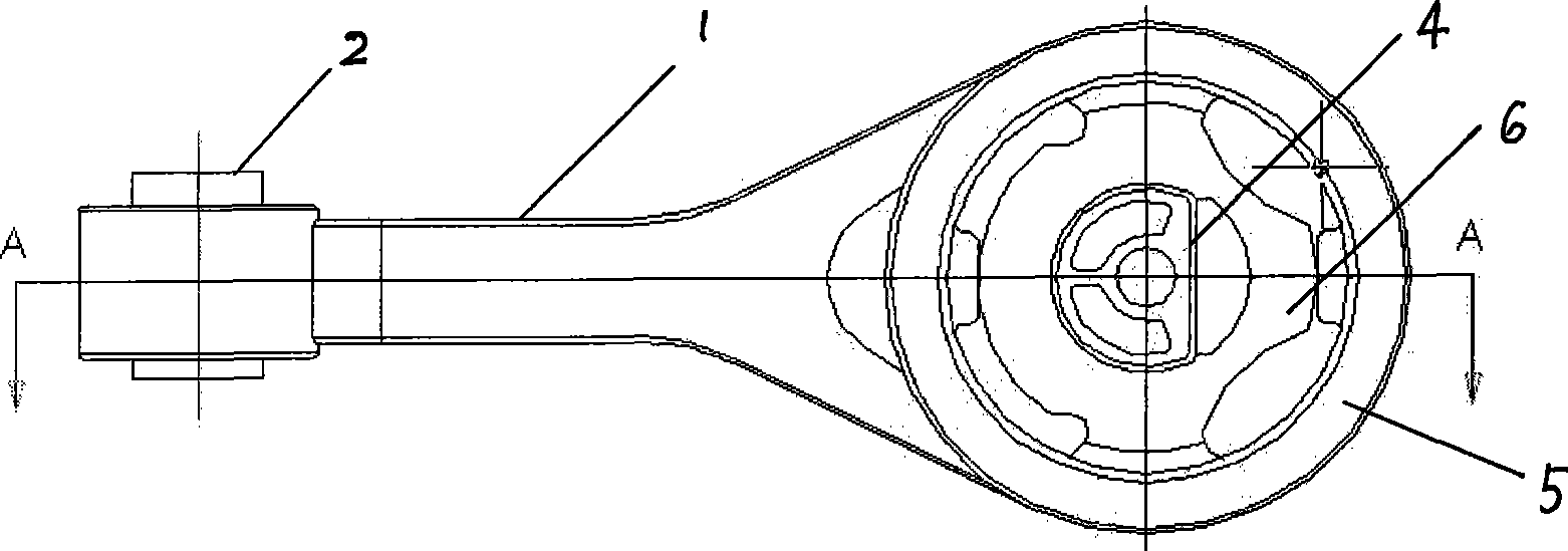
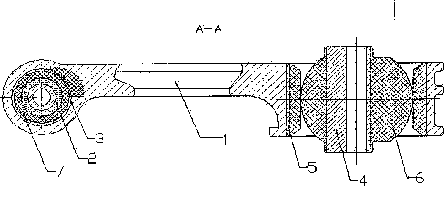
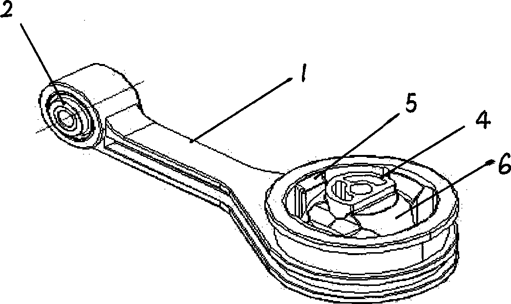
[0016] see figure 1 , figure 2 and image 3 , the rear suspension includes an aluminum alloy bracket 1, a small-end inner tube 2, a small-end bushing 3, a large-end inner tube 4, a big-end bushing 5, a large-end vibration-damping rubber 6, and a small-end vibration-damping rubber 7. The specific setting can be seen in the cross-sectional view of the large and small ends of the present invention. The small end inner t...


PUM


Abstract

The invention relates to an engine mounting structure which comprises an engine; the left side and the right side of the engine are connected with a vehicle body by a left mounting and a right mounting; the invention is characterized in that the rear lower end of the engine is connected with a rear mounting which is formed by respectively installing a bushing-typed structure at two ends of an aluminum alloy post; the big end of the aluminum alloy post is provided with a big end bushing-typed structure and the small end thereof is provided with a small end bushing-typed structure; a big end inner tube of the big end bushing-typed structure is connected with the vehicle body; a small end inner tube of the small end bushing-typed structure is connected with a side bracket of the engine; and the axes of the big end inner tube and the small end inner tube are mutually vertical. The invention can achieve traditional two-stage damping function which can only be achieved by a subframe, not only saves the layout space of an engine compartment, but also reduces the subframe, thereby greatly reducing the manufacturing difficulty and the manufacturing cost, and better meeting the needs for the NVH performance of the entire vehicle.

Description

technical field [0001] The invention belongs to the technical field of automobile engines, and in particular relates to an automobile engine suspension structure. Background technique [0002] In the past, ordinary engine mounts used a bushing structure, divided into front, rear, left, and right mounts. The left and right mounts were connected to the vehicle body, and the front or rear mounts were directly connected to the car floor. The level directly affects the NVH performance of the vehicle. As people have higher and higher requirements for vehicle NVH level and ride comfort, the previous layout and design can no longer meet the needs, so there is a secondary suspension vibration reduction, and now most of the sub-frames are used to realize this function. Currently, see Figure 5 , this type of structural arrangement is mostly the left and right mounts 13 and 14 are directly connected to the body, the front and rear mounts 8 are connected to the subframe 10, and the sub...

Claims


Application Information

Patent Timeline
IPC IPC(8): B60K5/12
Inventor 向以轩罗明英彭红
Owner CHONGQING CHANGAN AUTOMOBILE CO LTD
Features
  • Generate Ideas
  • Intellectual Property
  • Life Sciences
  • Materials
  • Tech Scout
  • Unparalleled Data Quality
  • Higher Quality Content
  • 60% Fewer Hallucinations
Learn More