
Integrated comprehensive heat management system for electric automobile

A technology of electric vehicles and management systems, applied in the direction of electric vehicles, vehicle energy storage, vehicle components, etc., can solve the problems of insufficient integration of thermal management systems, high energy consumption of vehicle thermal management systems, and unsatisfactory energy-saving effects. Achieve the effects of saving layout space, good economy and weight reduction

Pending Publication Date: 2020-02-21
SHANGHAI COTECH AUTOMOTIVE ENG CORP LTD
View PDF1 Cites 19 Cited by
  • Summary
  • Abstract
  • Description
  • Claims
  • Application Information

AI Technical Summary

Problems solved by technology

The energy-saving effect of most of the thermal management systems of electric vehicles currently on the market is not ideal. There are still many shortcomings in the design of the air-conditioning system, the thermal management system of the power battery pack, and the cooling system of the electric drive module, resulting in high or low ambient temperatures. When the energy consumption of the thermal management system of the whole vehicle is relatively large, the cruising range of the vehicle is greatly reduced
[0003] Chinese patent CN107097664A discloses an intelligent thermal management system for electric vehicles, including power battery packs, drive motors, motor controllers, on-board chargers, DC / DC voltage converters, battery radiators, battery coolers, and motor cooling Water pumps, electric oil pumps, expansion tanks, heaters, heat exchangers, electric compressors, condensers, liquid storage and drying pots, evaporators, electronic expansion valves, warm air cores, through pipelines and in pipelines The straight-through valve, three-way valve and four-way valve are connected to each other to form multiple thermal management control loops, which have achieved certain results in reducing the energy consumption of the vehicle, but the integration of the thermal management system is not high enough. The condenser, The battery heat sink and the heat sink are arranged in the same or close position, and cannot be integrated into the same component, resulting in high cost and weight, and will also affect each other and weaken their respective cooling performance

Method used


Image

  • Integrated comprehensive heat management system for electric automobile
  • Integrated comprehensive heat management system for electric automobile
  • Integrated comprehensive heat management system for electric automobile

Examples


Embodiment 1

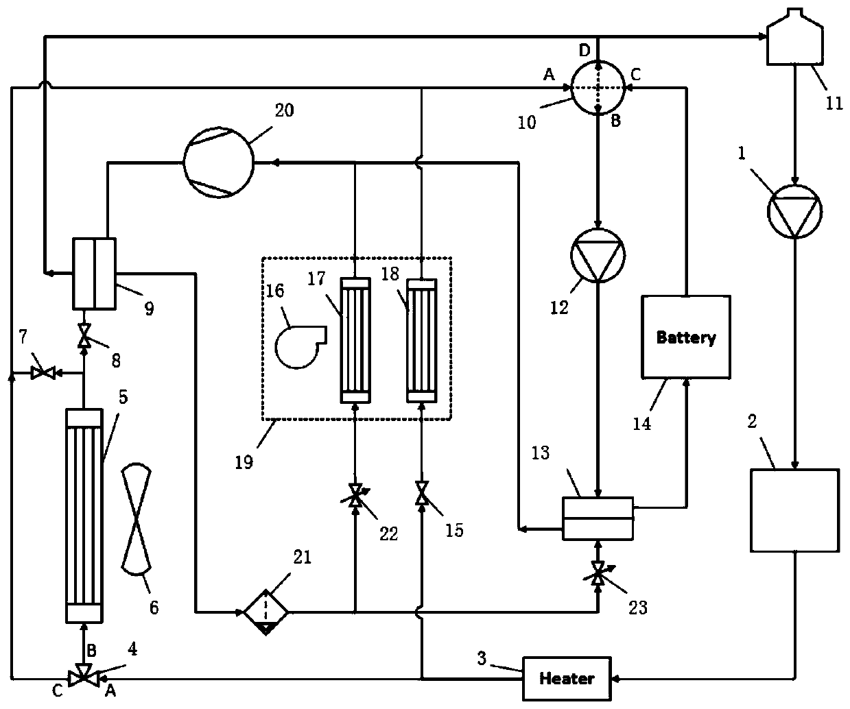
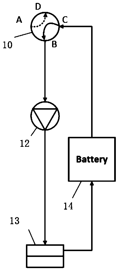
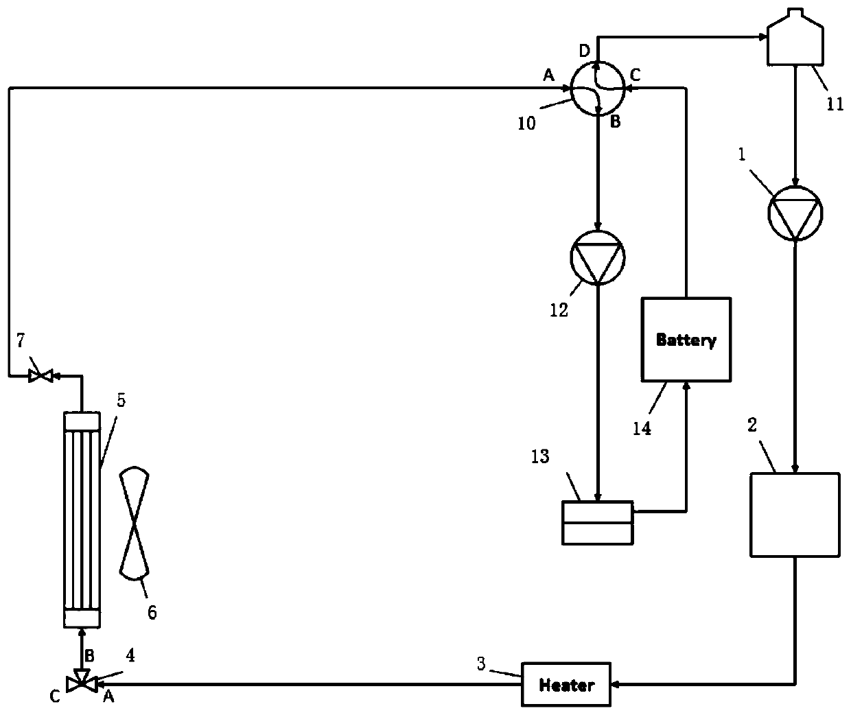
[0035] Such as figure 1 As shown, this application proposes an integrated thermal management system for electric vehicles, including a first water pump 1, an electric drive module 2, a heater 3, a radiator 5, a first heat exchanger 9, an expansion tank 11, and a second water pump 12. The second heat exchanger 13, the power battery pack 14, the evaporator 17, the warm air core 18, the air conditioner box 19, the electric compressor 20 and the liquid storage drying pot 21, each component passes through the pipeline and is installed in the pipeline The four-way valve 10, the three-way valve 4, the straight-through valve, and the expansion valve are connected to form a plurality of circuits that respectively perform thermal management and control on the power battery pack 14, the electric drive module 2, and the passenger compartment. The system sets an electric fan 6 next to the condenser for accelerating air flow to enhance heat exchange and is connected to the vehicle controlle...

Embodiment 2

[0056] Figure 12 Shown is another form of realization of the thermal management system of the present application. The heater 3 is arranged upstream of the branch road where the warm air core 18 is located. The water tank 11, the first water pump 1, the electric drive module 2, and the third straight-through valve 15 (the third straight-through valve 15 is opened at this time, and the port A of the three-way valve 4 is closed), then flows into the heater 3 to heat up, and then flows through the The warm air core 18, by turning on the electric blower 16, drives the airflow to be heated when passing through the warm air core 18, then flows into the passenger compartment for heating and heating, and finally passes through the four-way valve 10 (parallel mode, ports A and D are connected, ports B and C communicate) and get back to the expansion tank 11. And when the temperature of the power battery pack 14 is low and the heat generated by the electric drive module 2 cannot meet ...


PUM


Abstract

The invention relates to an integrated comprehensive heat management system for an electric automobile. The integrated comprehensive heat management system comprises a power battery pack temperature equalization loop, a power battery pack normal temperature cooling loop, a power battery pack air conditioner refrigeration circuit, a power battery pack heating loop, an occupant cabin air conditionerrefrigeration circuit, an occupant cabin heating loop and an electric drive module cooling loop; and the power battery pack normal temperature cooling circuit, the power battery pack air conditionerrefrigeration circuit, the electric drive module cooling circuit and the occupant cabin air conditioner refrigeration circuit share a radiator for heat exchange, an inlet side pipeline of the radiatoris connected with an outlet side pipeline of an electric drive module through a three-way valve, and an outlet side pipeline of the radiator is connected with the power battery pack normal temperature cooling circuit or the electric drive module cooling circuit through a first through valve. According to the integrated comprehensive heat management system, compared with the prior art, through thedesign of the integrated optimized heat management loop, a condenser of the air conditioning system is eliminated, the number of front-end module radiators is reduced, the arrangement space is saved,and the system has the advantages of cost reduction, weight reduction and energy consumption reduction.

Description

technical field [0001] The invention relates to the technical field of thermal management of electric vehicles, in particular to an integrated comprehensive thermal management system for electric vehicles. Background technique [0002] At this stage, there are some technical bottlenecks in electric vehicles, and electric vehicle users are faced with the problems of charging anxiety and range anxiety. In order to increase the cruising range of electric vehicles as much as possible, electric vehicles are required to be energy-efficient as much as possible. Designing a more energy-efficient thermal management system is one of the important means to increase the cruising range. The energy-saving effect of most of the thermal management systems of electric vehicles currently on the market is not ideal. There are still many shortcomings in the design of the air-conditioning system, the thermal management system of the power battery pack, and the cooling system of the electric driv...

Claims


Application Information

Patent Timeline
Patent Type & Authority Applications(China)
IPC IPC(8): B60H1/00B60H1/14B60L58/26B60L58/27
CPCB60H1/00278B60H1/00392B60H1/143B60L58/26B60L58/27B60H2001/00307Y02T10/70
Inventor 夏应波包益民
Owner SHANGHAI COTECH AUTOMOTIVE ENG CORP LTD
Learn More