Magnetic weft insertion method of circular knitting machine

A circular knitting machine and magnetic technology, applied in circular looms, looms, textiles, etc., can solve the problems of weaving yarn damage, the influence of the application field expansion of weaving products, and the limitation of yarn types, so as to avoid friction and extrusion , increase mechanical properties, expand the effect of application fields

Inactive Publication Date: 2009-04-01
JIANGNAN UNIV
View PDF0 Cites 7 Cited by
  • Summary
  • Abstract
  • Description
  • Claims
  • Application Information

AI Technical Summary

Problems solved by technology

[0003] In order to overcome the shortcomings of existing circular knitting machines, such as the extrusion of warp yarns caused by the weft insertion transmission device, the damage to the knitting y

Method used


Image

  • Magnetic weft insertion method of circular knitting machine

Examples


Embodiment Construction

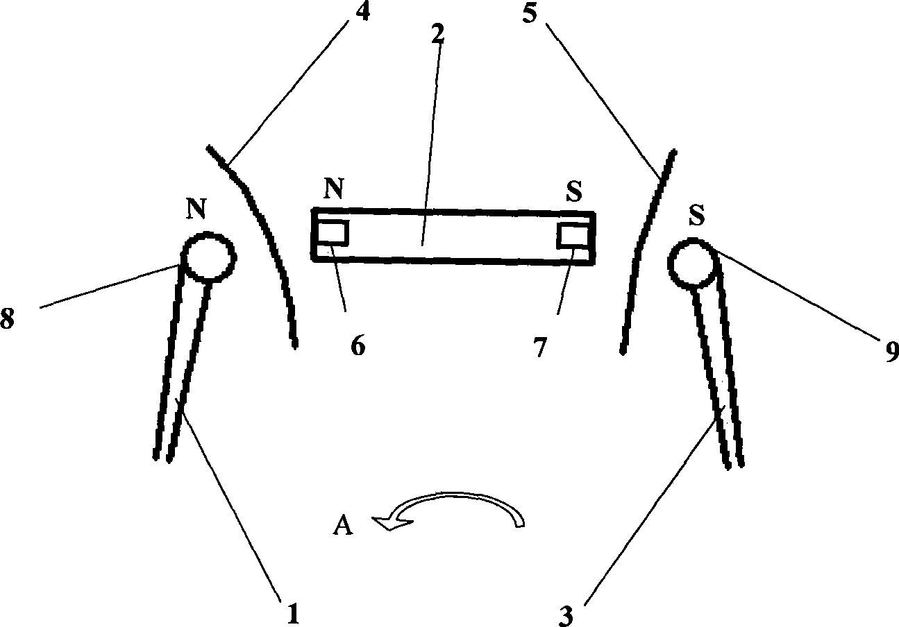
[0009] figure 1 It is a schematic diagram of the weft insertion device of the magnetic circular knitting machine according to the embodiment of the present invention. figure 1 Among them, a permanent magnet 6,7 is respectively installed on both sides of the weft shuttle boat 2, and the magnet 6 on one side of the advancing direction is installed as N pole outwards, and then the other side magnet 7 is installed S pole outwards. Using the principle of same-sex repulsion, a magnet 8 is installed at the position where the shuttle bar 1 is originally in contact with the weft shuttle ship 2, and the N pole of the magnet 8 is facing the weft shuttle ship 2, and the shuttle pusher 3 is originally in contact with the weft shuttle ship. A piece of S pole is installed toward the magnet 9 of weft yarn shuttle boat 2. Thereby make the both sides of weft yarn shuttle boat 2 keep a certain distance with shuttle pusher 3 and shuttle bar 1 all the time, and warp yarn 4,5 can pass through at t...


PUM


Abstract

The invention relates to a magnetic weft inserting method of a round braider. A group of magnets are respectively arranged at the front and the rear sides of a weft shuttle, namely, the contact part of a shuttle pushing device and a shuttle blocking rod, by utilizing the principle of homosexual repulsion, to keep a certain distance between the weft shuttle and the shuttle pushing device and between the weft shuttle and the shuttle blocking rod so as to prevent the direct contact, extrusion and abrasion of warp yarns, thereby being capable of widening the choosing scope of the yarn types of the round braider, improving the mechanical performance of a fabric and developing the application field of the fabric.

Description

Technical field [0001] The invention relates to a circular knitting machine, in particular to a magnetic weft insertion method for a circular knitting machine. Background technique [0002] At present, the known weft insertion device of the circular knitting machine mainly consists of a weft yarn shuttle boat, a shuttle pusher and a shuttle bar. Generally, the circular knitting machine is provided with four, six or eight weft yarn shuttle boats, and each weft yarn shuttle boat is then installed in the upper and lower tracks of an orbital circle at an appropriate angle according to its number, and the orbital circle is located on The outer side of the timing disk is connected with a power mechanism at the bottom of the timing disk, so as to provide the timing disk for rotation. In addition, a shuttle pusher and a shuttle bar are arranged on both sides of the shuttle frame corresponding to each weft shuttle boat on the timing disk, wherein the shuttle pusher mainly pushes the...

Claims


Application Information

Patent Timeline
IPC IPC(8): D03D49/24D03D37/00
Inventor 周罗庆宋海花
Owner JIANGNAN UNIV
Why Eureka
Try Eureka