Rotating dynamical type multiphase booster pump

A technology of rotary power and booster pump, applied in the field of multiphase pump, can solve the problems of limited use range, reduced efficiency, large volume and other problems of multiphase pump, and achieve the effect of good performance under variable working conditions and convenient disassembly, assembly and maintenance.

Active Publication Date: 2010-09-15
CHINA NAT OFFSHORE OIL CORP +1
View PDF0 Cites 0 Cited by
  • Summary
  • Abstract
  • Description
  • Claims
  • Application Information

AI Technical Summary

Problems solved by technology

But so far, the performance of multiphase booster pumps is far from meeting the actual needs of the oil field. On the one hand, due to the complexity of multiphase flow and the dependence of the pump on the flow state and gas content The range of application is still limited; on the other hand, the performance and efficiency of the multiphase pump under the condition of high inlet gas-liquid ratio need to be improved. When the inlet gas volume content reaches 50%, the best efficiency of the screw axial flow pump is only About 45%, while the twin-screw multiphase pump is sensitive to solid particles on the one hand, and at the same time has a large volume. After the volume content of the imported gas exceeds 70%, its efficiency also decreases rapidly. At the same time, the multiphase pump also faces the problem of dry running resistance. , sealing, lubrication and a series of technical issues

Method used


Image

  • Rotating dynamical type multiphase booster pump
  • Rotating dynamical type multiphase booster pump
  • Rotating dynamical type multiphase booster pump

Examples


Embodiment Construction

[0020] The technical solution of the present invention will be described in detail below with reference to the drawings and embodiments.

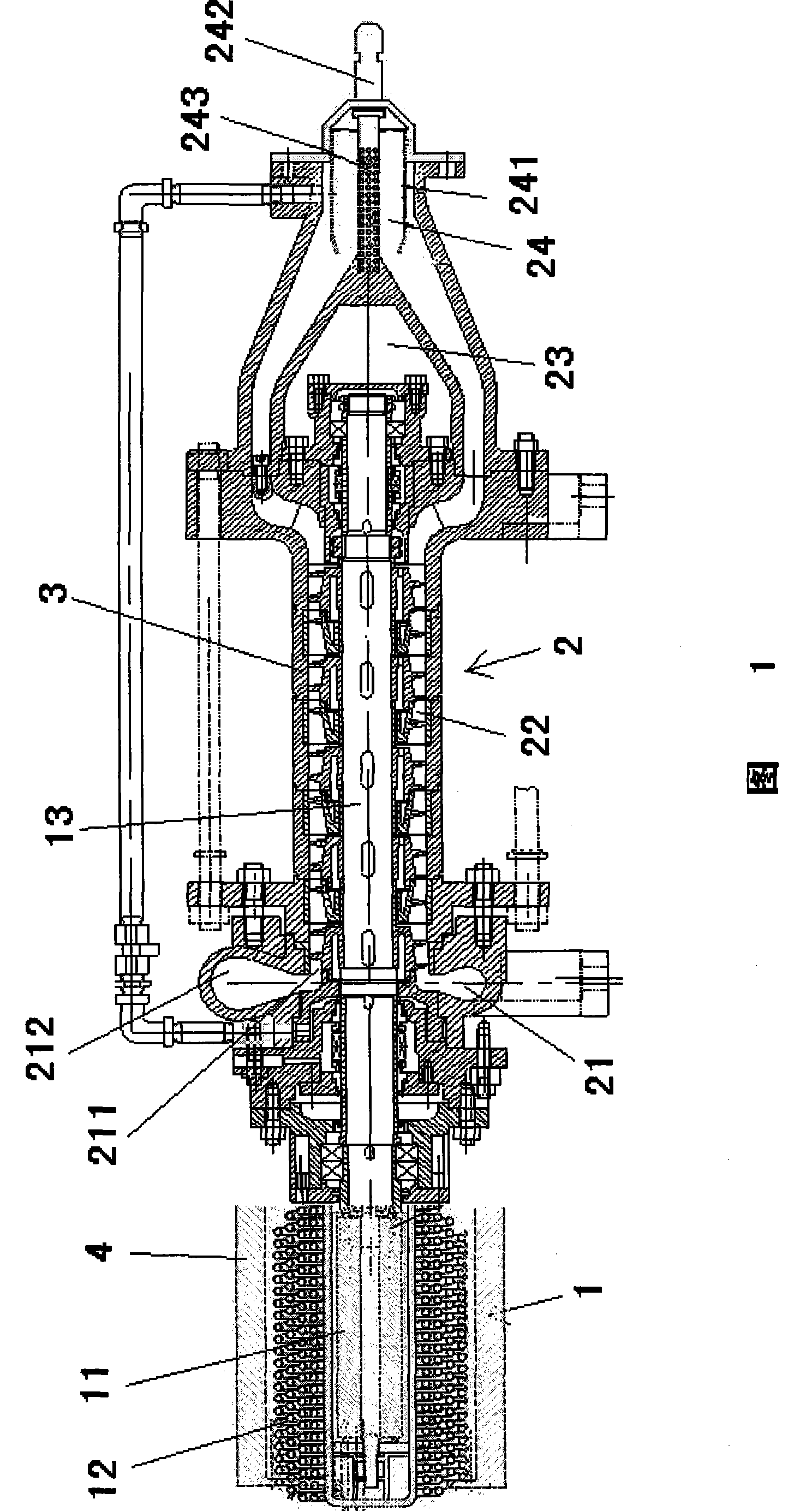
[0021] As shown in Figure 1, the present invention is a shaft connection structure, including a power unit 1, a pump body 2 driven and connected by the power unit 1, and other auxiliary devices, such as bearings, auxiliary fixing parts, connectors, and sealing systems , Lubrication system, etc.

[0022] The power device 1 of the present invention is driven by a high-speed frequency conversion explosion-proof motor 11. In order to effectively absorb the heat generated by the motor 11 due to its operation, a cooling coil 12 is provided on the periphery of the motor 11. The motor 11 is electrically connected with pressure, temperature, flow and other measurement and control devices installed at the inlet and outlet of the pump body 2. The operator can control the motor 11 through the operation panel connected with the measurement and control device...


PUM


Abstract

The invention relates to a rotating dynamic multiphase pressure pump which comprises a pump body connected with a dynamic device and a sectional pump shell outside the pump body. The pump body comprises a homogenization unit, an intake unit, a pressurization unit and a diffusion unit. The homogenization unit has a buffer tank, the centre of which a polyporous separation tube is inserted in; the upper terminal of the separation tube passes through the buffer tank and the lower terminal is fixed to the intake unit. The intake unit comprises a water guiding wimble which is fixed on the pump shaft and is provided with a homogenization blade. The pressurization unit comprises at least two stages impeller and a series structure formed by interstage adjustors. The impeller is fixed on the pump shaft with a tapered wheel hub which is provided with the blade outside and the impeller rotates with the pump shaft; the interstage adjustor comprises the wheel hub which is interstitially sleeved with the pump shaft and is provided with a guide blade; outside the guide blade, a sleeve is fixed and the sleeve is fixed on the pump shell to the guide blade; therefore, the interstage adjustor can notrotate with the pump shaft. The diffusion unit comprises a diffuser and a discharge chamber. The pressure pump enables the oil-gas-water multiphase flow to pressurize without separation and realizes the economic production of the marginal oil field, nearby oil field and deepwater oil field.

Description

Technical field [0001] The invention relates to a multiphase pump, in particular to a rotary power type multiphase booster pump. Background technique [0002] At the end of the 1980s, as the petroleum industry shifted from land to oceans and deserts with relatively harsh natural environments, oil and gas field development also shifted from relatively concentrated large oil and gas fields to small marginal oil and gas fields and satellite oil and gas fields, with multiphase booster pumps as the core remote The mixed transportation technology of transporting untreated oil, gas and water multiphase well flow has attracted wide attention from major oil companies with its significant technical advantages and considerable economic benefits. However, due to the complexity of multiphase flow and the limitations of our understanding of multiphase flow, in the long-distance transportation process of oil, gas and water multiphase well flow, the traditional gas and liquid separation is carri...

Claims


Application Information

Patent Timeline
Patent Type & Authority Patents(China)
IPC IPC(8): F04D31/00F04D13/06F04D29/40F04D29/24
Inventor 李清平薛敦松朱宏武王建丰朱海山王涛姚海元王珏王胜
Owner CHINA NAT OFFSHORE OIL CORP
Why Eureka
Try Eureka