
Blade type oil, gas and water multiphase booster pump

An oil-gas-water, vane-type technology, applied in the field of multi-phase booster pump, vane-type oil-gas-water multiphase booster pump, can solve the problems of sensitivity to solid particles, large size and weight, loss of pressurization ability, etc., to improve performance , saving equipment and pipeline construction costs, and optimizing the effect of design

Inactive Publication Date: 2006-11-22
CHINA UNIV OF PETROLEUM (BEIJING) +1
View PDF0 Cites 0 Cited by
  • Summary
  • Abstract
  • Description
  • Claims
  • Application Information

AI Technical Summary

Problems solved by technology

[0005] The multiphase pumps developed in China are basically volumetric multiphase pumps. Taking the twin-screw multiphase pump as an example, its typical characteristics are medium and small flow rates and medium to high pressure. The experimental prototype of the twin-screw pump multiphase pump currently developed in my country Most of them are low-to-medium pressurized and sensitive to solid particles. Under the same design conditions, compared with vane machines, their size and weight are larger; for traditional vane pumps, due to the centrifugal force during high-speed rotation, they have Liquids and gases with different properties are prone to phase separation, which leads to a sharp decrease in the efficiency of the pump or even failure to work under the condition of gas-liquid two-phase flow. When the volume content of the inlet gas reaches 4%, the efficiency of the conventional centrifugal pump decreases rapidly. , when the inlet gas volume content exceeds 10%, it basically cannot operate; when the inlet gas content exceeds 20%, the efficiency of the axial flow pump decreases sharply until it loses its boosting capacity

Method used


Image

  • Blade type oil, gas and water multiphase booster pump
  • Blade type oil, gas and water multiphase booster pump
  • Blade type oil, gas and water multiphase booster pump

Examples


Embodiment Construction

[0038] The technical scheme of the present invention is described in detail below in conjunction with accompanying drawing:

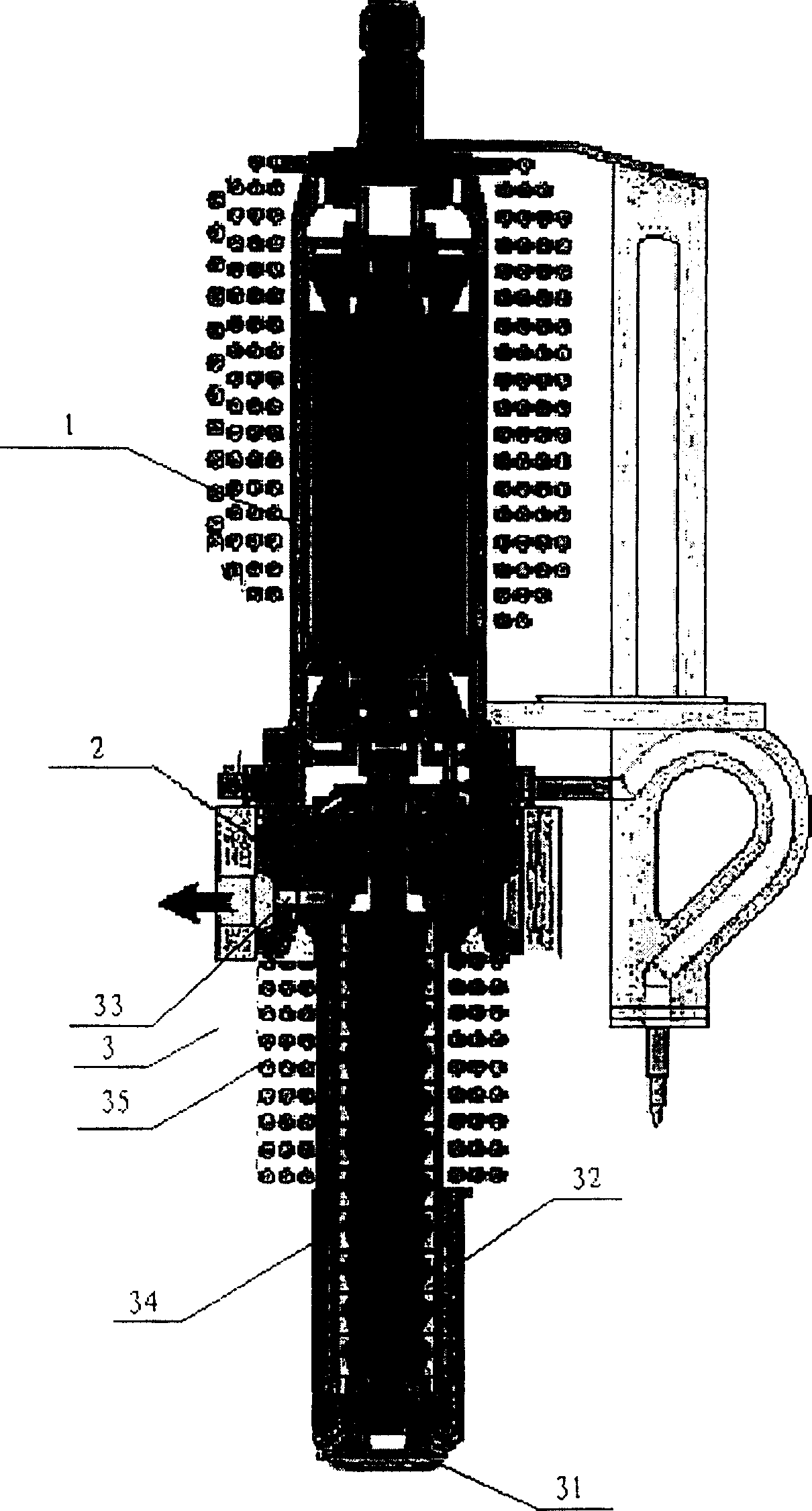
[0039] Such as figure 1As shown, it is a structural schematic diagram of the vane type oil-gas-water multiphase booster pump of the present invention. It can be seen from the figure that in order to adapt to the application of offshore platforms and future deep-water oil fields, the entire vane multiphase pump adopts a vertical design, mainly composed of a power unit 1, a seal, a bearing unit 2 and a booster unit 3, and the power unit 1 passes through the seal. , the bearing device 2, the shaft coupling and the supercharging device 3 are connected. The multi-phase booster pump requires the rotating shaft to rotate at high speed, so usually the power unit 1 adopts a high-speed frequency conversion explosion-proof motor.

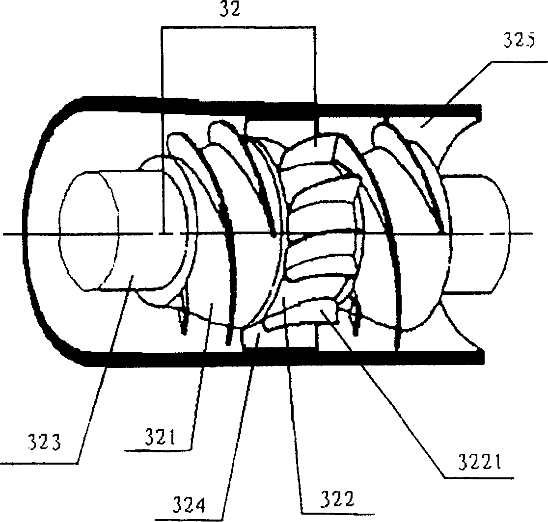
[0040] The supercharging device 3 includes a suction unit 31, a multiphase supercharging unit 32, a final diffuser section 33, a pum...


PUM


Abstract

A vane type oil-gas-water multiphase booster pump, comprising at least a booster device, a bearing and a sealing device, and a power device, the booster device and the rotating shaft of the power device are arranged concentrically, and are fixed on the respective rotating shafts through the bearing and the sealing device , the supercharging device is connected with the power unit through a coupling, the power unit drives the supercharging device to work, the multiphase fluid is boosted in the supercharging device and then output, and the supercharging device is a suction unit, a multiphase supercharging unit, The final diffuser and pressure chamber. The invention takes into account the performances of both the vane pump and the compressor, and the optimized vane multiphase pump can avoid or delay the occurrence of phase separation between gas and liquid in the flow channel of the impeller, improving the performance of the vane pump when transporting multiphase fluids; It adopts an open structure, and a sand discharge hole is set on the pump casing, which can be used to transport mixed media containing sand; the power drive device adopts a frequency conversion device, cooperates with a multiphase fluid buffer homogenizer and an automatic monitoring system to ensure that the multiphase pump has good work efficiency. condition performance.

Description

Technical field: [0001] The invention relates to a multiphase booster pump, in particular to a vane type oil-gas-water multiphase booster pump, which belongs to the technical fields of mechanical manufacturing and multiphase flow. Background technique: [0002] In the late 1980s, with the transformation of the oil industry from land to oceans and deserts with relatively harsh natural environments, from relatively concentrated large oil and gas fields to the development of small marginal oil and gas fields and satellite oil fields, long-distance Oil and gas multiphase mixed transportation technology, which transports untreated multiphase well flow, has attracted extensive attention from major oil companies for its remarkable technical advantages and considerable economic benefits. However, due to the complexity of multiphase flow and the limitations of our understanding of multiphase flow, in the long-distance transportation of oil, gas and water multiphase well flow, the tra...

Claims


Application Information

Patent Timeline
Patent Type & Authority Patents(China)
IPC IPC(8): F04D29/54E21B43/00
Inventor 朱宏武李清平薛敦松
Owner CHINA UNIV OF PETROLEUM (BEIJING)
Learn More