LED illuminating device

A light-emitting device, LED chip technology, applied in lighting devices, lighting device parts, semiconductor devices of light-emitting elements, etc., can solve problems such as discomfort, human eye glare, eye fatigue, etc.

Inactive Publication Date: 2009-04-01
CONTREL TECH CO LTD
View PDF1 Cites 14 Cited by
  • Summary
  • Abstract
  • Description
  • Claims
  • Application Information

AI Technical Summary

Problems solved by technology

When there is a strong light source directly reaching the eyes, in order to reduce the amount of incoming light, the pupils will naturally narrow, and the visual power will be reduced, so the eye muscles will be tense, resulting in an uncomfortable feeling in the eyes, which will cause the image to become blurred, and then cause reading problems. Difficulties such as fatigue and eye fatigue
At present, the lens used in LED is to concentrate the light source to achieve a better light source intensity, which is easy to cause glare to the human eye and cause discomfort

Method used


Image

  • LED illuminating device
  • LED illuminating device
  • LED illuminating device

Examples


Embodiment Construction

[0028] In order to describe the structure and characteristics of the present invention in detail, the following two preferred embodiments are given below and described in conjunction with the drawings, wherein:

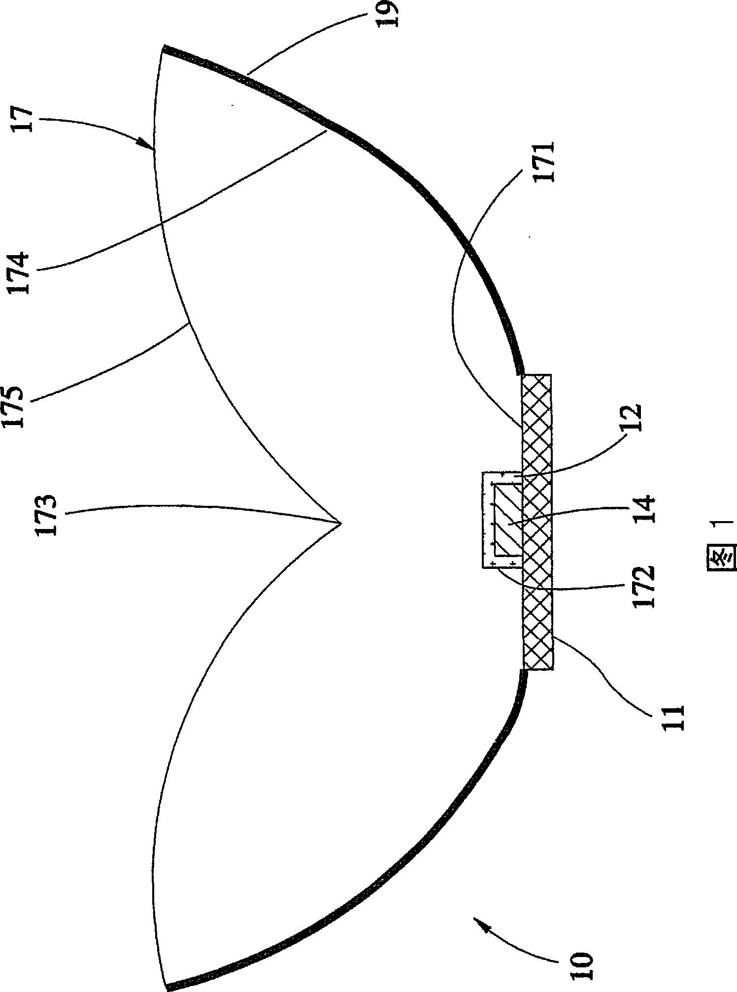
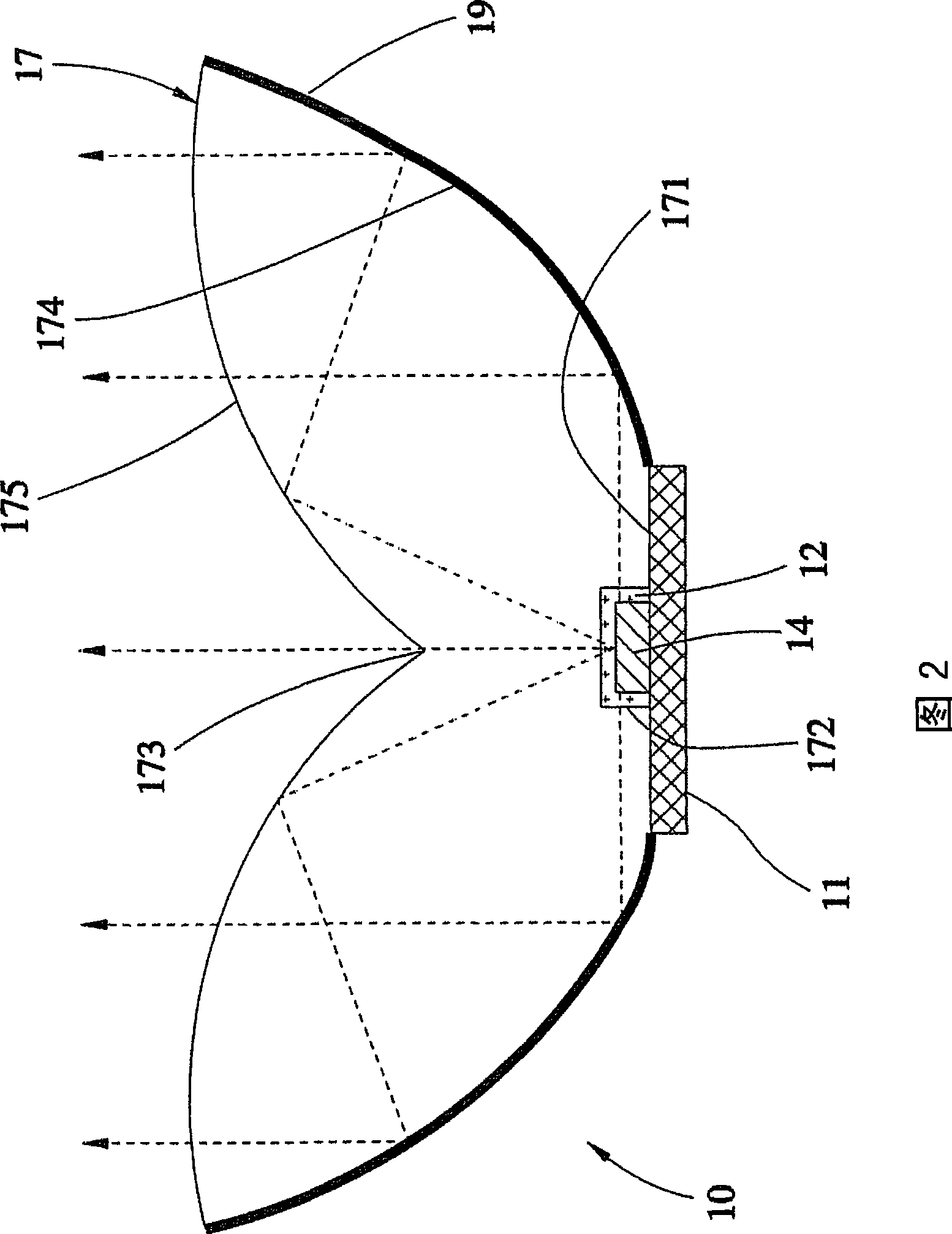
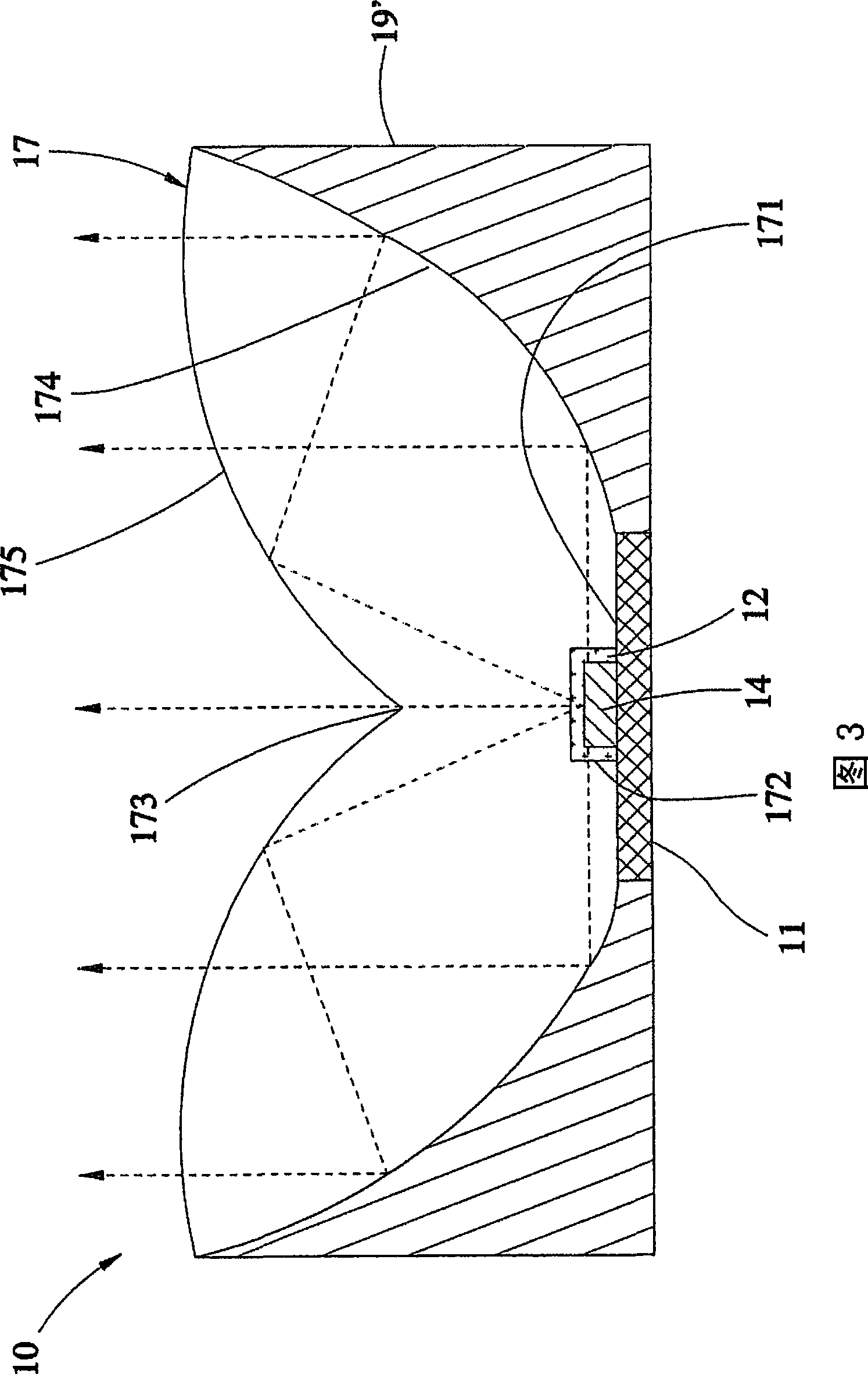
[0029] As shown in Figures 1 to 2, an LED lighting device 10 provided by the first preferred embodiment of the present invention is mainly composed of a substrate 11, an LED chip 14 and a lens 17, wherein:

[0030] The LED chip 14 is disposed on the substrate 11 .

[0031] The lens 17 has a mounting portion 171 on the bottom surface, and the mounting portion 171 has a groove 172 recessed upward. The lens 17 is arranged on the substrate 11 with its mounting portion 171, and the LED chip 14 is located in the groove 172. Inside. In actual manufacture, a buffer layer 12 can be arranged between the LED chip 14 and the lens 17, and its material can be silica gel or epoxy resin or other soft light-transmitting substances, and the buffer layer 12 is shown in each figure. Lo...


PUM


Abstract

The invention relates to an LED device which comprises a basic plate, an LED chip arranged on the basic plate, and a lens which is provided with an upward groove at the bottom and arranged on the basic plate by the bottom thereof, wherein, the LED chip is positioned in the groove; an axial point which is arranged at the top of the lens is positioned over the LED chip; the top face of the lens forms a semi-reflecting surface along the axial point towards the outward periphery; light emitted by the LED chip enters into the lens and is reflected to other parts of the lens when the incident angle thereof on the semi-reflecting surface is larger than a predetermined angle, and passes through the semi-reflecting surface when the incident angle thereof is smaller than the predetermined angle. In such a way, the effect of uniform light can be achieved and further the glare is avoided. In addition, due to simple structure, the manufacturing cost of the LED device is less.

Description

technical field [0001] The invention relates to a light-emitting component, in particular to an LED light-emitting device capable of emitting relatively uniform light. Background technique [0002] Early LEDs (Light Emitting Diodes) had low output light source intensity and limited application levels. Recently, LED manufacturers have developed high-brightness LEDs under the continuous innovation and research and development of LED manufacturers. However, the existing high-brightness LEDs are still equipped with traditional LED lenses, which excessively control the light source direction of the LED, resulting in the existing lens concentrating the intensity of the LED light source in the central area, making the light emitted by the LED narrow and long. The light type, so the illuminance on the viewing surface is not uniform. [0003] It can be seen from the structure of the existing high-brightness LED that the light emitted by the LED chip needs to be reflected by the refl...

Claims


Application Information

Patent Timeline
Patent Type & Authority Applications(China)
IPC IPC(8): F21V5/04F21V13/04F21Y101/02F21Y115/10
Inventor 萧德瑛吴威宏彭柏翰
Owner CONTREL TECH CO LTD
Why Eureka
Try Eureka