
Auxiliary overlap joint hydraulic match grinding process for spool valve of servo valve

A technology of spool valve pair and servo valve, which is applied in the field of matching grinding process of servo valve spool valve pair overlap, which can solve the problems of no curve interpretation, complex structure of servo valve, not easy to block, etc., and achieve equipment testing The effect of faster speed, less repeated testing, and improved grinding efficiency

Active Publication Date: 2009-04-08
BEIJING RES INST OF PRECISE MECHATRONICS CONTROLS
View PDF0 Cites 12 Cited by
  • Summary
  • Abstract
  • Description
  • Claims
  • Application Information

AI Technical Summary

Problems solved by technology

The structure of the servo valve is complicated, and there are many oil passage holes and intersecting holes on the shell, which are not easy to block and easily cause leakage, making measurement difficult.
[0003] Since the gas distribution measurement uses low-pressure gas as the measurement medium, it is easy to block the outside and the test is simple and clean. Influenced by it, the grinding curve is not linear enough, and the test results are not accurate enough
At the same time, there are problems such as slow test speed and poor repeatability in gas distribution measurement, resulting in low production efficiency
[0004] Hydraulics and Pneumatics, 1999, 000 (002), "Microcomputer-controlled Servo Valve Hydraulic Grinding Precision Measurement Technology"; author Zhang Jianfeng, "Research on Servo Valve Hydraulic Grinding Technology" involves hydraulic grinding technology, but This article mainly explains from the establishment of a computer platform to automatically draw curves, including two parts of test equipment and test software. It does not involve how to interpret the curve, nor does it disclose how to perform sealing installation and other related content

Method used


Image

  • Auxiliary overlap joint hydraulic match grinding process for spool valve of servo valve
  • Auxiliary overlap joint hydraulic match grinding process for spool valve of servo valve
  • Auxiliary overlap joint hydraulic match grinding process for spool valve of servo valve

Examples


Embodiment Construction

[0021] The hydraulic matching grinding process of the lap joint of the servo valve spool valve pair is as follows:

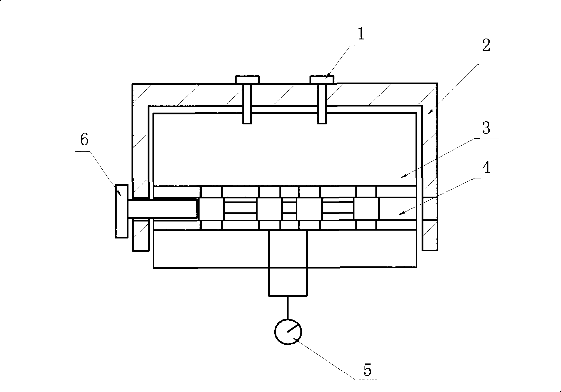
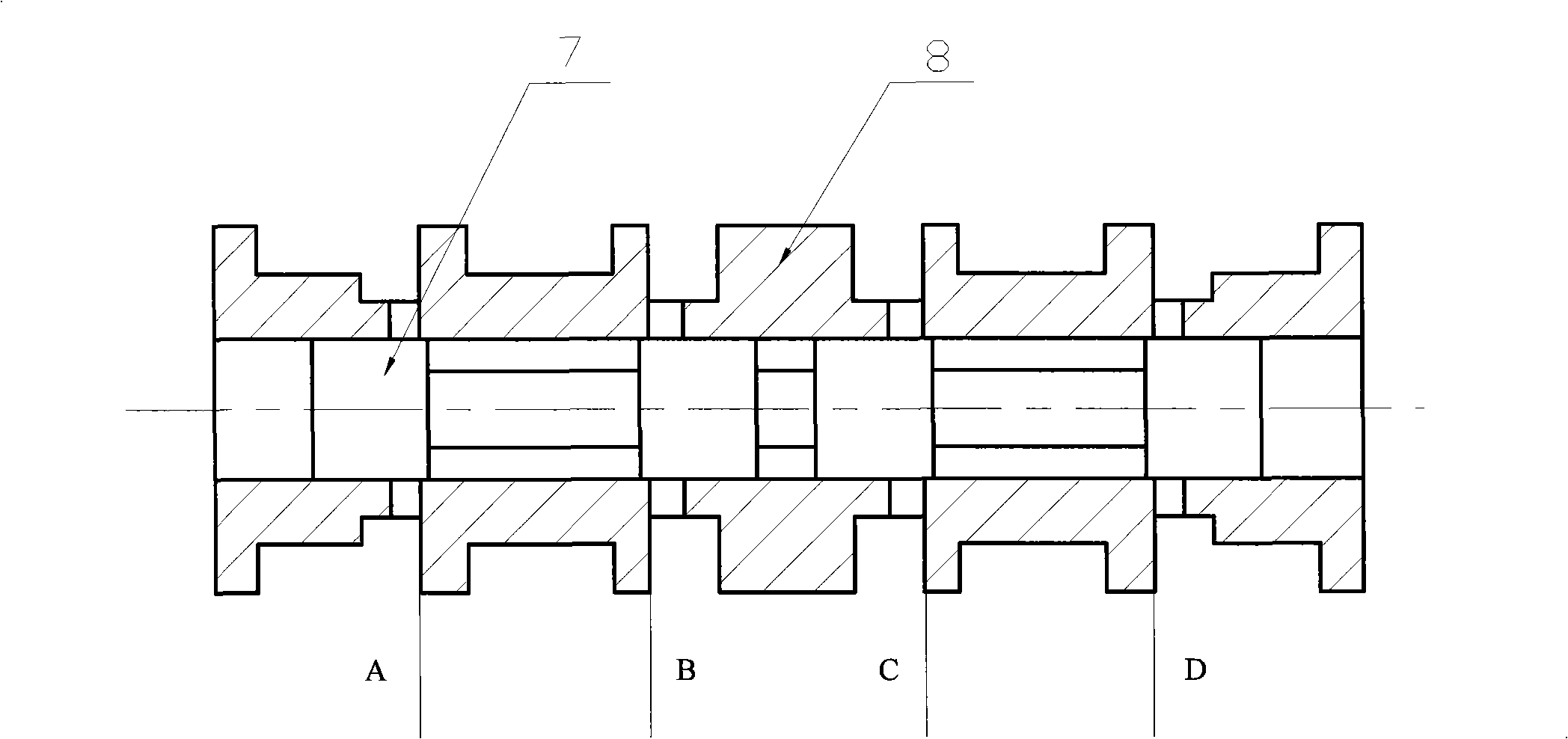
[0022] (1) if figure 1 As shown, the servo valve spool pair 4 is installed in the process shell 3, and the oil passages on the process shell 3 are sealed by using the sealing plug and the integral pressure sleeve 2, and the integral pressure sleeve 2 and the process shell 3 It is fixed by the fastening screw 1, the displacement sensor 6 is installed at one end of the servo valve spool, and the flow sensor 5 is installed in the feedback chamber of the spool valve pair. The schematic diagram of the spool valve pair is as follows figure 2 As shown, where A, B, C, D represent the working side of the slide valve pair;

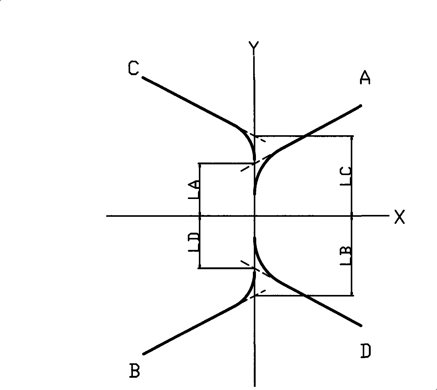
[0023] (2) supply oil to the spool valve pair 4, start the test, drag the servo valve spool 7 back and forth, draw the matching grinding curve of the spool valve pair 4 working side according to the displacement sensor 6 and the flow sensor 5 collec...


PUM


Abstract

The invention relates to a hydraulic match grinding process for the lap amount of a slide valve pair of a servo valve. The process comprises the following steps: (1). the slide valve pair of the servo valve is arranged in a process shell; a sealing gland and a whole pressing sleeve are adopted to seal each oil circuit of the process shell; a displacement sensor is arranged on one end of a valve core of the servo valve; and a flow sensor is arranged in a feedback cavity of the slide valve pair; (2). oil is supplied to the slide valve pair; when a test is begun, the valve core of the servo valve is dragged to and fro; and according to collecting values of the displacement sensor and the flow sensor, a match grinding curve of a working side of the slide valve pair is drawn; (3). the match grinding curve is judged and read; a value of the lap amount of the working side of the slide valve side is judged and is compared with the design requirement of the servo valve; and the working side corresponding to the value larger than the design requirement is sharpened and grinded; and (4). the steps from the step (2) are carried out repeatedly till the slide valve pair meets the design requirement.

Description

technical field [0001] The invention relates to a matching grinding process for the overlapping joint amount of a slide valve pair of a servo valve. Background technique [0002] The spool valve pair is the power amplification stage of the servo valve, and its dynamic and static quality has a great influence on the dynamic and static quality of the entire servo valve. The structure of the servo valve is complicated, and there are many oil passage holes and intersecting holes on the shell, which are not easy to block and easily cause leakage, making measurement difficult. . [0003] Since the gas distribution measurement uses low-pressure gas as the measurement medium, it is easy to block the outside and the test is simple and clean. However, due to the influence of the stability of the pressure difference near the zero position, the gas distribution curve is not linear enough, and the test results are not accurate enough. At the same time, there are problems such as slow t...

Claims


Application Information

Patent Timeline
IPC IPC(8): B24B15/08
Inventor 姜晓颖张弨丁忠军陈悦李鸿雁刘燕敏项迎
Owner BEIJING RES INST OF PRECISE MECHATRONICS CONTROLS
Learn More