Inking pot

An ink fountain, ink line technology, applied in workshop equipment, manufacturing tools, etc., can solve problems such as poor ink fountain, assembly operations, increase in the number of parts, cutting, etc., to save installation and replacement effort, and reduce the number of parts. Simplify, improve safety effect

Inactive Publication Date: 2009-04-08
LEIYU SHANGHAI PACKAGING PROD
View PDF2 Cites 3 Cited by
  • Summary
  • Abstract
  • Description
  • Claims
  • Application Information

AI Technical Summary

Problems solved by technology

[0014] Thereby, in order to release the loading of the coil spring, it must be operated with both hands in view of its structure. Therefore, in the following problems, for example, due to grasping the pillar with one hand in an unstable workplace, the balance of the operator himself is maintained. to make the ink line, so the ink fountain that has to be operated with two hands is not good
[0015] Also in the following problem: the connecting surface between the above-mentioned first clutch member and the second clutch member is formed with a helicoid that engages with each other, so it is necessary to form the thickness of the helical surface, and these clutch members cannot be too miniaturized (thin). wall)
There are also problems in that when the seal and the throttle member are assembled into the ink fountain, the throttle member is several millimeters in size, poor operability, increased assembly work and the ...

Method used


Image

  • Inking pot
  • Inking pot
  • Inking pot

Examples


Embodiment 1

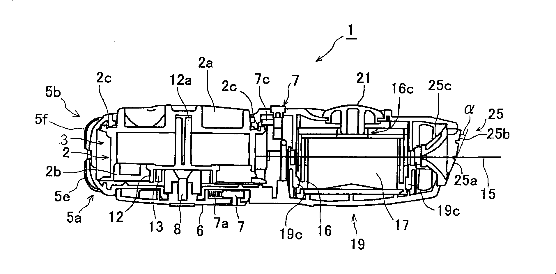
[0082] Such as figure 1 As shown, the ink fountain 1 of the present invention has a spool 3 for accommodating the spool 2 wound with an ink thread 15 at the rear, and a storage chamber 29 (ink chamber) for supplying ink to the ink thread 15 drawn out from the ink fountain 1 .

[0083] (ink thread winding shaft)

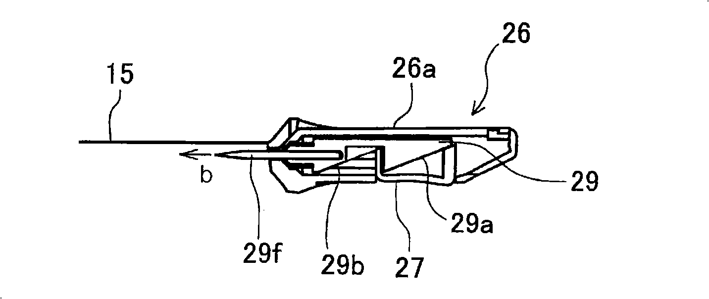
[0084] The above scroll 2 as image 3 The ink thread 15 is wound on the outer peripheral surface of the main body of the reel, and the coil spring 4 is housed in the inner periphery of the main body of the reel, and is closed by the shaft cover 5b. In addition, a holding portion 12a for holding the inner peripheral end of the above-mentioned coil spring 4 is formed on one end side, and a first ratchet 12 is rotatably mounted on the other end side to hold the inner peripheral end of the above-mentioned coil spring 4. The first ratchet 12 is formed with a Engagement recessed part 12b which engages with engagement claw 13b of the 2nd ratchet 13 mentioned later.

[008...


PUM


Abstract

An ink fountain allows ink lines wrapped on the scroll body to contact with ink immersing components immersed with ink; uses a needle component to pierce into the surface of timber or the like objects; performs ink lines on the object surface; arranges a coil spring in the internal circumstance of the scroll body for rollback ink lines, wherein, a rotor plate for storing power for the coil spring is configured to expose from the upper surface of the body; and provides a block on the rotor plate for limiting the rollback of the coil spring, wherein, the block is introduced to freely project from and fall back to the lateral surface of the rotor plate, and is blocked to a blocking dent provided on the body side through a force application apparatus. The invention provides an ink fountain in which the load application of coil spring of the revolution axis can be easily released only by a hand, and the ink will not stick on the fingers upon replacing the ink immersing components.

Description

technical field [0001] The invention relates to an ink fountain for drawing ink lines by plucking ink lines soaked in ink with fingers in construction engineering to touch the object surface of the ink lines such as wood. Background technique [0002] In the past, in construction projects, etc., an ink fountain was used as a tool for drawing straight lines on surfaces such as wood and concrete. The ink fountain was used to insert a needle assembly tied with an ink line soaked in ink into the target surface of wood, etc., and pull it out with fingers. An ink line resting between the ink fountain and the needle assembly, the ink line comes into contact with the surface of the object to draw the ink line. [0003] This type of ink fountain is provided with a spool (spool) around which the long and thin ink thread can be retracted, and an ink-soaked member for stably supplying the ink to the ink thread. The ink thread drawn from the ink fountain contacts the ink-soaked member. ...

Claims


Application Information

Patent Timeline
IPC IPC(8): B25H7/04
Inventor 佐藤哲史
Owner LEIYU SHANGHAI PACKAGING PROD
Why Eureka
Try Eureka