Portal crane

A gantry hoist and gantry technology, which is applied in water conservancy projects, marine engineering, coastline protection and other directions, can solve problems such as unfavorable saving of project investment, operation at work sites, and increase of project investment, etc. The effect of convenient maintenance and saving project investment

Inactive Publication Date: 2010-03-17
水发机电集团有限公司
View PDF0 Cites 4 Cited by
  • Summary
  • Abstract
  • Description
  • Claims
  • Application Information

AI Technical Summary

Problems solved by technology

Ordinary gantry hoists generally can only walk along a single-direction linear track to lift multiple gates of a sluice, and its working range is small
When there are multiple sluices in the upstream and downstream of the pivot project, it is necessary to add multiple hoists, which greatly increases the project investment; and these hoists cannot work at work sites within different straight line ranges due to the limitation of the working range , so the equipment utilization rate is very low, which is not conducive to saving engineering investment

Method used


Image

  • Portal crane
  • Portal crane
  • Portal crane

Examples


Embodiment 1

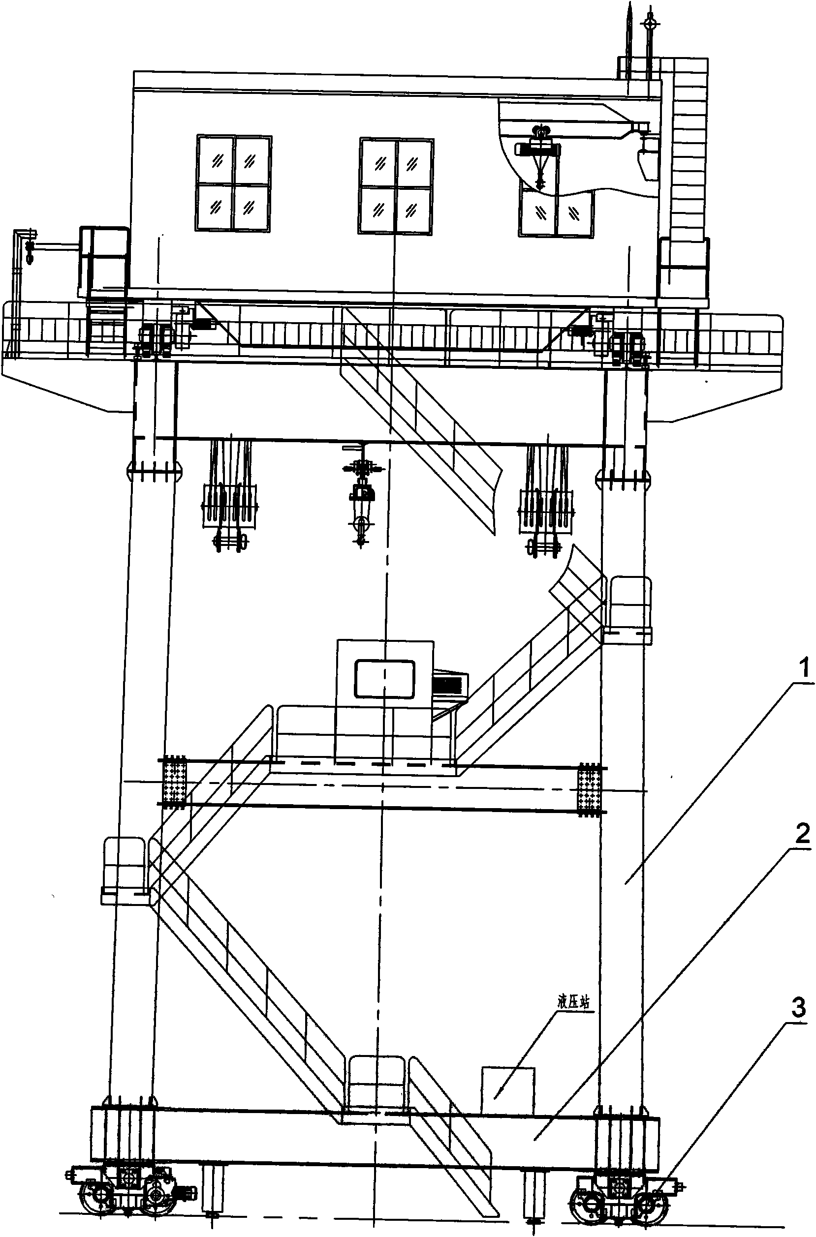
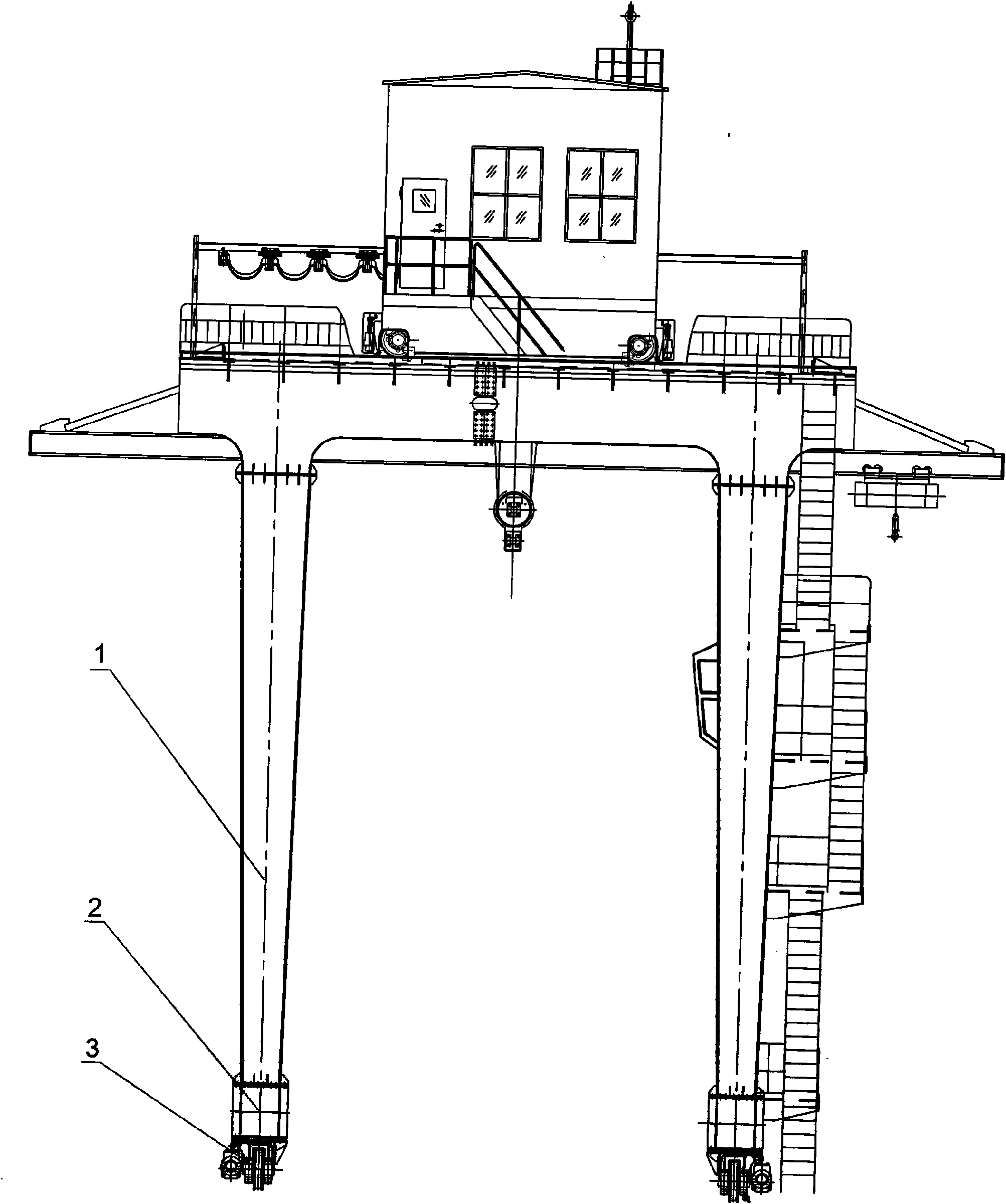
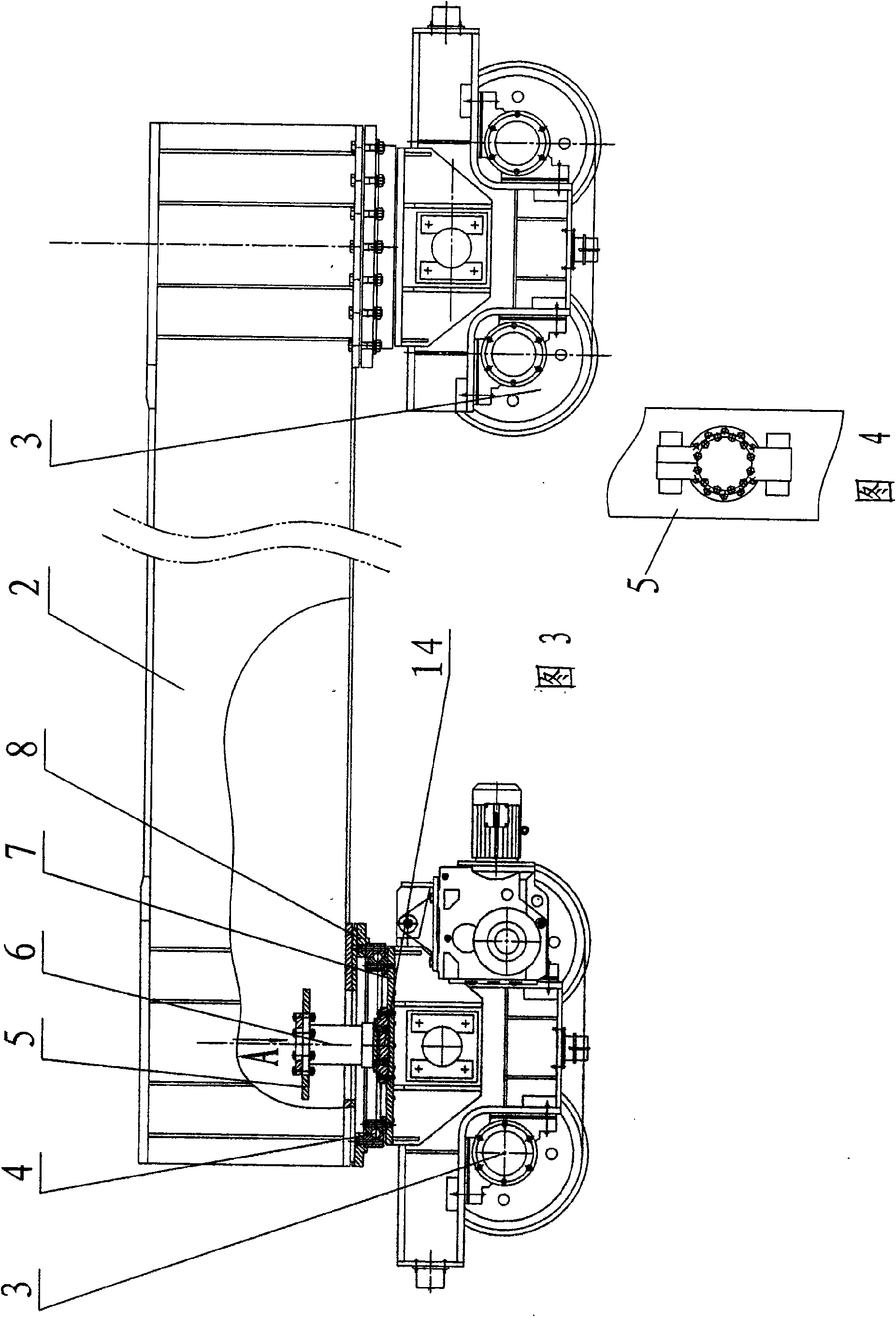
[0022] as attached figure 1 , figure 2 , image 3 , Figure 4 As shown, a gantry hoist includes a gantry 1 and a main traveling mechanism located at the bottom of the gantry 1. The gantry 1 is provided with a lifting mechanism, which adopts the prior art. The main traveling mechanism comprises 4 wheel sets 3, and the top of each wheel set 3 is provided with a top plate 7, and the top plate 7 of each wheel set 3 is provided with a slewing bearing 4. The slewing bearing 4 is a slewing bearing, its inner ring is fixedly connected with the top plate 7 of the wheel set through screws, its outer ring is connected with the connecting plate 8 through screws, and the connecting plate 8 is connected with the bottom beam 2 through bolts. The output end of the swing oil cylinder 6 is fixedly connected with the top plate 7 through the connecting plate 14 , and its cylinder body is fixed on the bottom beam 2 through the connecting steel plate 5 .

[0023] Under the action of pressure o...

Embodiment 2

[0029] as attached figure 1 , figure 2 , Figure 5 , Figure 6 As shown, this embodiment is basically the same as Embodiment 1, except that the rotary mechanism in this embodiment adopts a structure in which a reciprocating mechanism drives a link mechanism to move. Its rotary mechanism comprises hydraulic oil cylinder 11, connecting rod 10 and rotary shaft 9. One end of the rotary shaft 9 is fixedly connected with the top plate 7 of the wheel set 3 , the other end is connected with the connecting rod 10 , the cylinder body of the hydraulic cylinder 11 is fixedly connected with the bottom beam 2 , and its cylinder rod is connected with the connecting rod 10 . In this embodiment, through the reciprocating motion of the hydraulic cylinder, the connecting rod 10 and the rotary shaft 9 connected thereto are driven to rotate, thereby driving the wheel set to rotate, and realizing the steering of the main traveling mechanism of the gantry hoist. In this embodiment, the reciproc...

Embodiment 3

[0032] as attached figure 1 , figure 2 , Figure 7 , Figure 8 As shown, this embodiment is basically the same as Embodiment 1, except that the outer ring of the slewing support 4 in this embodiment is a gear-type structure. The inner ring of the slewing support 4 is fixedly connected to the connecting plate 8 by screws, and its outer ring is fixedly connected to the top plate 7 by screws. The outer ring of the slewing bearing 4 is driven by a rack 12 meshed with its gear teeth. The rack 12 is connected with the cylinder rod of the hydraulic cylinder 11, and the cylinder body of the hydraulic cylinder 11 is fixed on the bottom beam 2.

[0033] In this embodiment, the rack 12 reciprocates under the action of the cylinder rod of the hydraulic cylinder 11, driving the outer ring of the slewing bearing 4 to rotate, thereby driving the wheel set 3 to rotate, and realizing the steering of the main traveling mechanism of the door machine.

[0034] In this embodiment, the mechan...


PUM


Abstract

The invention discloses a portal hoist which belongs to the technical field of hydraulic equipment and comprises a main walking mechanism, wherein the main walking mechanism is arranged at the lower part of a bottom crossbeam of a portal crane and comprises at least four wheel sets, a pivoting support is arranged at the top of each wheel set, an inner rim and an outer rim of the pivoting support are respectively connected with the bottom crossbeam of the portal crane and the top plates of the wheel sets, and the pivoting supports and the wheel sets are driven to rotate through a swing mechanism fixedly connected with the bottom crossbeam. The wheel sets are driven to rotate through the swing mechanism so as to realize the turning of the wheel sets, thereby realizing the turning of the mainwalking mechanism of the portal crane, leading the portal crane to conveniently reach working sites on different straight lines for working, realizing the purpose that one portal hoist can carry outhoisting or equipment loading and unloading for the sluice gates of multiple buildings at different positions of one hydraulic and hydroelectric pivotal project, and greatly saving the project investment.

Description

technical field [0001] The invention relates to a door hoist, which belongs to the technical field of hydraulic equipment. Background technique [0002] Gate hoist is a commonly used hoisting mechanical equipment in water conservancy and hydropower projects, which is used to open or close gates or for equipment loading and unloading. Ordinary gantry hoists generally can only walk along a single-direction linear track to lift multiple gates of a sluice, and its working range is small. When there are multiple sluices in the upstream and downstream of the pivot project, it is necessary to add multiple hoists, which greatly increases the project investment; and these hoists cannot work at work sites within different straight line ranges due to the limitation of the working range , so the equipment utilization rate is very low, which is not conducive to saving engineering investment. Contents of the invention [0003] Aiming at the above-mentioned defects existing in the prio...

Claims


Application Information

Patent Timeline
Patent Type & Authority Applications(China)
IPC IPC(8): E02B7/36
Inventor 杜培文高峰许志刚祝凤山王晶刘天政
Owner 水发机电集团有限公司
Why Eureka
Try Eureka