Front frame of refrigerated container

A technology of refrigerated container and front frame, which is applied in the direction of packaging, transportation and packaging, and transportation of passenger cars. The effect of refueling frequency

Active Publication Date: 2009-04-08
CHINA INTERNATIONAL MARINE CONTAINERS (GROUP) CO LTD +1
View PDF0 Cites 6 Cited by
  • Summary
  • Abstract
  • Description
  • Claims
  • Application Information

AI Technical Summary

Problems solved by technology

[0002] At present, most of the existing refrigerated containers use diesel-electric dual-power coolers to refrigerate the containers. The fuel required for refrigeration of the coolers is diesel oil. Therefore, it is necessary to install an oil tank on the container to provide the fuel required for the cooler. Due to the small volume of the oil tank The size directly affects the normal operation time of the cooling machine after one injection, so the size of the inner volume of the fuel tank is particularly critical, but in the existing design, the front frame structure is as follows figure 1 As shown, the front end upper beam 13, the middle beam 1, the front lower beam 3 and the inner and outer panels 2 and 4 of the front wall are arranged in sequence. From the appearance, a plane is formed at the front end of the container, and the cooling machine is arranged on the outer panel of the front wall The upper part of the cooler, the oil tank is located under the cooler, since the cooler occupies most of the front frame area, the oil tank located under the cooler is relatively small in design volume, and the normal working time of the cooler after one injection is less than Cargo transportation time, failure to refuel during transportation will cause cargo damage and other problems, which will bring economic losses and affect the image of the transportation company

Method used


Image

  • Front frame of refrigerated container
  • Front frame of refrigerated container
  • Front frame of refrigerated container

Examples


Embodiment Construction

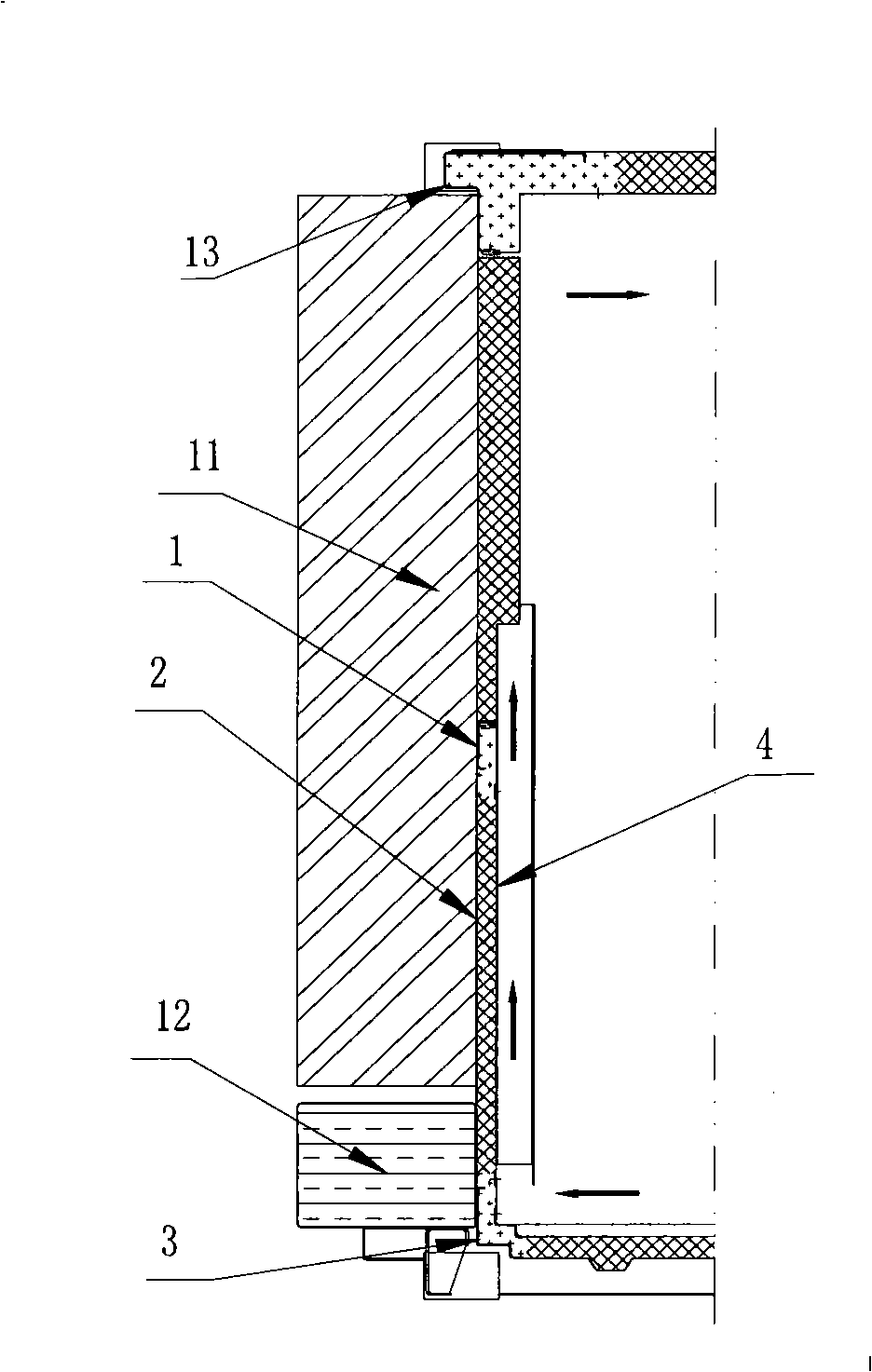
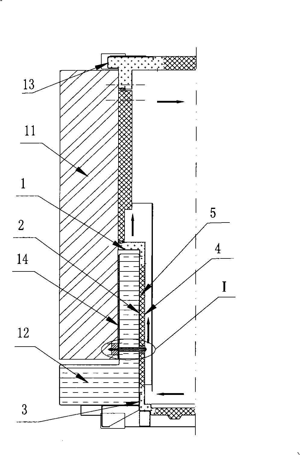
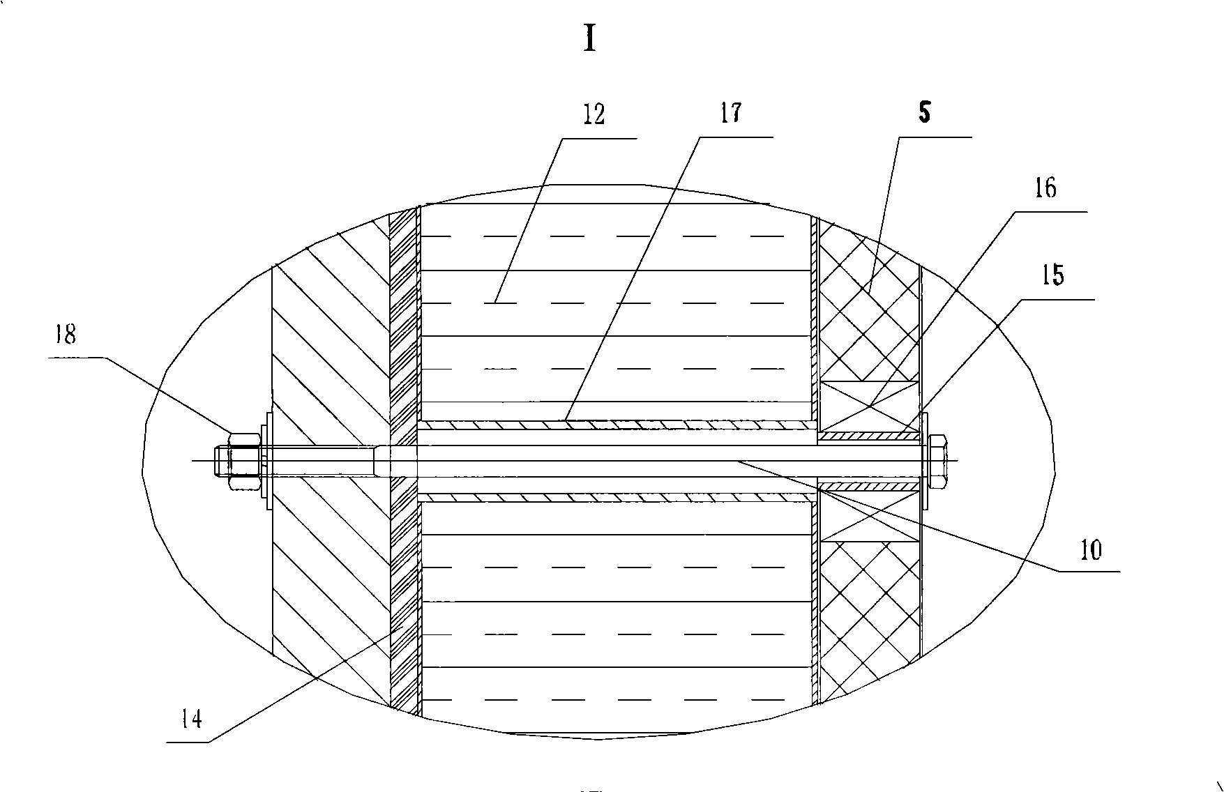
[0015] Such as figure 2 , 3 As shown, a refrigerated container front frame includes a front upper beam 13, a middle beam 1, a front lower beam 3, the three of which are connected by the front wall outer panel 2, the front wall inner panel 4, and become a whole. An insulation layer 5 is provided between the plates 2, 4, and the inner and outer plates 2, 4 of the front wall are divided into upper and lower parts by the middle beam 1. The middle beam 1 is a special-shaped beam bent inward, and its cross section is Shape, a cavity is formed between the middle beam 1, the lower part of the cooler 11 and the outer panel 2 of the front wall, and the fuel tank 12 is The vertical part of the upper part of the oil tank 12 is set in the cavity between the middle beam 1, the cooler 11, and the outer panel 2 of the front wall. The lower part of the cooler 11 is fixed to the inner and outer panels of the front wall by a fixing member that crosses the fuel tank. On 2, 4, there are two fixing ...


PUM


Abstract

The invention discloses a front frame of a refrigerated container, which comprises a front end upper beam, a middle beam and a front end lower beam which are connected into a whole through a front wall outside plate and a front wall inside plate. An insulting layer is arranged between the front wall outside plate and the front wall inside plate; the upper part of the outside of the front wall outside plate is provided with a cooling machine, while the lower part is provided with an oil tank; the middle beam is a deformed beam bended inwardly; a cavity is formed between the middle beam and the lower part of the cooling machine as well as the front wall outside plate; and the upper part of the oil tank is arranged in the cavity. The front frame increases the oil tank capacity, saves cost and realizes nonrefuelling during the middle and long distance transportation on the premise of not changing the strength and the function of the container.

Description

Technical field [0001] The invention relates to a refrigerated container, in particular to a front frame of the refrigerated container. Background technique [0002] At present, the existing refrigerated containers mostly use diesel-electric dual-power refrigerators to refrigerate the containers. The fuel required for the refrigerator refrigeration is diesel. Therefore, it is necessary to install a fuel tank on the container to provide the fuel required by the refrigerator. The size directly affects the normal operation time of the cooler after one injection, so the internal volume of the fuel tank is particularly critical. However, in the existing design, the front frame structure is like figure 1 As shown, the front-end upper beam 13, the middle beam 1, and the front-end lower beam 3 are arranged in sequence with the inner and outer panels 2, 4 of the front wall. From the appearance, a plane is formed at the front end of the container, and the cooler is arranged on the outer p...

Claims


Application Information

Patent Timeline
Patent Type & Authority Applications(China)
IPC IPC(8): B65D88/74B65D90/02
Inventor 黄田化黄国浩马兆云赵玉亮
Owner CHINA INTERNATIONAL MARINE CONTAINERS (GROUP) CO LTD
Why Eureka
Try Eureka