
Arrangement structure of engine valve actuating mechanism

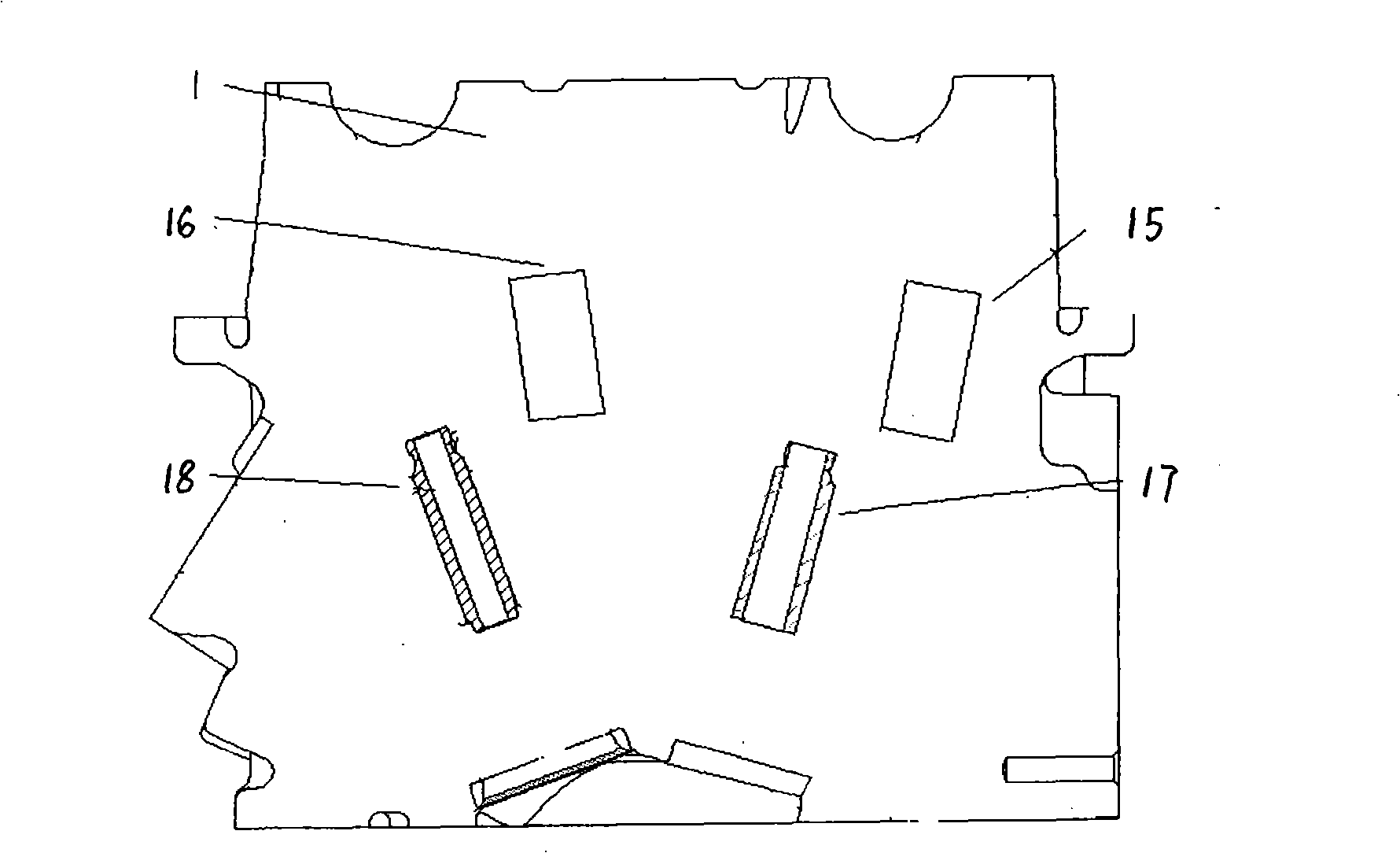
A technology of gas distribution mechanism and layout structure, which is applied in the direction of engine components, machines/engines, valve devices, etc., and can solve the problems of increasing the time and cost of the cylinder head machine, and the angle of the tool cannot be unified.

Inactive Publication Date: 2009-04-08
CHONGQING CHANGAN AUTOMOBILE CO LTD
View PDF0 Cites 2 Cited by
  • Summary
  • Abstract
  • Description
  • Claims
  • Application Information

AI Technical Summary

Problems solved by technology

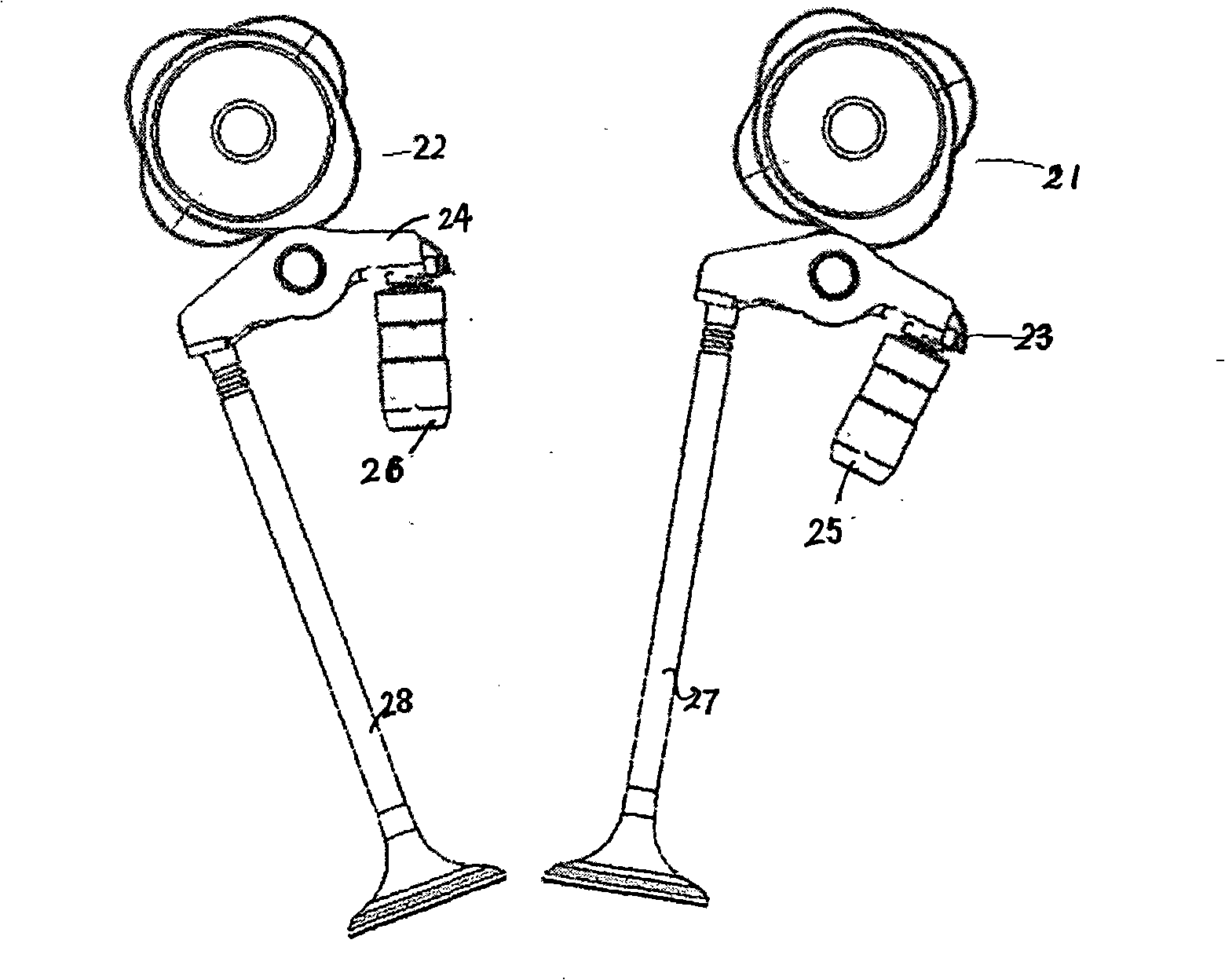
see figure 1 , because intake hydraulic tappet assembly 26, exhaust hydraulic tappet assembly 25, intake valve 28, exhaust valve 27 correspond to intake hydraulic tappet hole 16, exhaust hydraulic tappet hole 15 on the cylinder head , intake valve guide hole 18, exhaust valve guide hole 17 have different angles with the horizontal direction, so that when the cylinder head is machining these holes, the angle of the cutting tool to machine the holes cannot be uniform, and each After machining one type of hole, it is necessary to adjust the angle of the tool. For example, because the angle between the exhaust hydraulic tappet hole and the intake hydraulic tappet hole is different from the horizontal direction, after machining the intake hydraulic tappet hole , it is necessary to adjust the tool angle to machine the exhaust hydraulic tappet hole, which will inevitably increase the time and cost of cylinder head machining

Method used


Image

  • Arrangement structure of engine valve actuating mechanism
  • Arrangement structure of engine valve actuating mechanism
  • Arrangement structure of engine valve actuating mechanism

Examples


Embodiment Construction

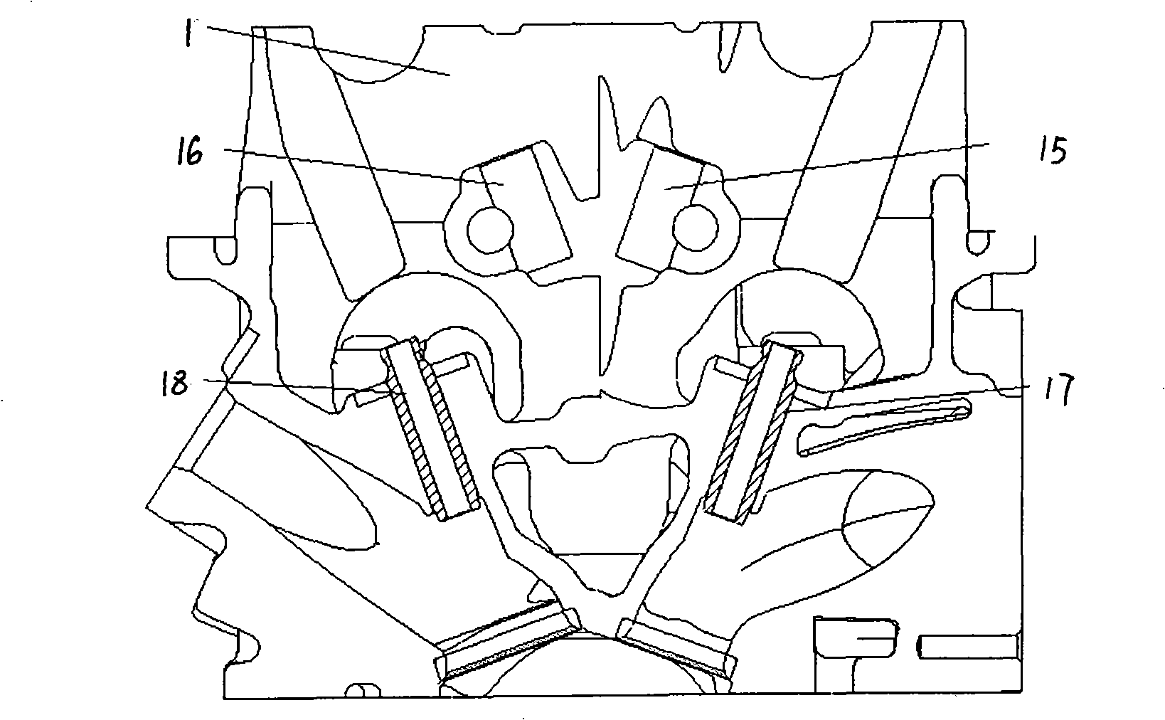
[0013] see image 3 The cylinder head 1 of the arrangement structure proposed by the present invention is to arrange the intake hydraulic tappet hole 16 and the intake valve guide hole 18 in parallel in each group (only one group is shown in the figure), and the exhaust hydraulic tappet hole 15 and the intake valve guide hole 18 are arranged in parallel. The exhaust valve guide holes 17 are arranged in parallel. And the intake hydraulic tappet hole 16 and the exhaust hydraulic tappet hole 15 in each group are symmetrically arranged along the same central line A perpendicular to the horizontal plane; the intake valve guide hole 18 and the exhaust valve guide hole 17 are also arranged vertically The same central line A of the horizontal plane is symmetrically arranged left and right.

[0014] For valve trains mounted in the cylinder head see Figure 4 , the intake hydraulic tappet assembly 26 is arranged parallel to the intake valve 28, the exhaust hydraulic tappet assembly 25...


PUM


Abstract

The invention provides the arrangement structure of a valve actuating mechanism of an engine, comprising a cylinder cover and the valve actuating mechanism installed on the cylinder cover; the structure is characterized in that: each group of air intake hydraulic tappet holes for installing the valve actuating mechanism on the cylinder cover are arranged in parallel with air intake valve guide pipe holes, the installed air intake hydraulic tappet of the valve actuating mechanism and the air inlet valve are also mutually parallel; each group of air exhaust hydraulic tappet holes and the air exhaust valve guide pipe holes are arranged in parallel, and the installed air exhaust hydraulic tappet and the air exhaust valve are also mutually parallel. The arrangement structure changes the difficulties of frock change and cutter change when the traditional cylinder cover is designed and processed so as to cause the use of the same frock and cutter during mechanical processing, thus greatly shortening the cost and the mechanical processing time.

Description

technical field [0001] The invention relates to an engine, in particular to the improvement of the cylinder head structure of the engine. Background technique [0002] The structure of the cylinder head of the engine matches the structure of the valve train. In the engine's valve train system, the layout of the valve train components should not only ensure that each cylinder is well ventilated, the inflation efficiency should be as high as possible, and the performance development of the engine should be improved as much as possible, but also the current technological level is not enough. influences. [0003] The traditional arrangement of the valve train is as follows: figure 2 As shown, the intake hydraulic tappet assembly 26 and the intake valve 28 are not arranged in parallel, and there is an angle; similarly, the exhaust hydraulic tappet assembly 25 and the exhaust valve 27 are not arranged in parallel, and the intake valve 28 and the The exhaust valves 27 are also n...

Claims


Application Information

Patent Timeline
Patent Type & Authority Applications(China)
IPC IPC(8): F01L1/14
Inventor 谌伦武成卫国苏继才张青梁文锋
Owner CHONGQING CHANGAN AUTOMOBILE CO LTD
Learn More