Inflating apparatus

A technology of an inflatable device and a control device, which is applied to pump devices, liquid variable displacement machines, non-variable displacement pumps, etc., and can solve problems such as low efficiency, unfavorable air leakage, and failure of air compressors

Active Publication Date: 2009-04-08
周文三
View PDF0 Cites 4 Cited by
  • Summary
  • Abstract
  • Description
  • Claims
  • Application Information

AI Technical Summary

Problems solved by technology

[0003] Although commonly used air compressors can generate high-pressure gas for inflating, however, the gas flow rate it can generate is small. When it is used in objects that require a large amount of inflation (such as rubber boats), it takes a long time to inflate and the efficiency is low. In addition,...

Method used


Image

  • Inflating apparatus
  • Inflating apparatus
  • Inflating apparatus

Examples


Embodiment Construction

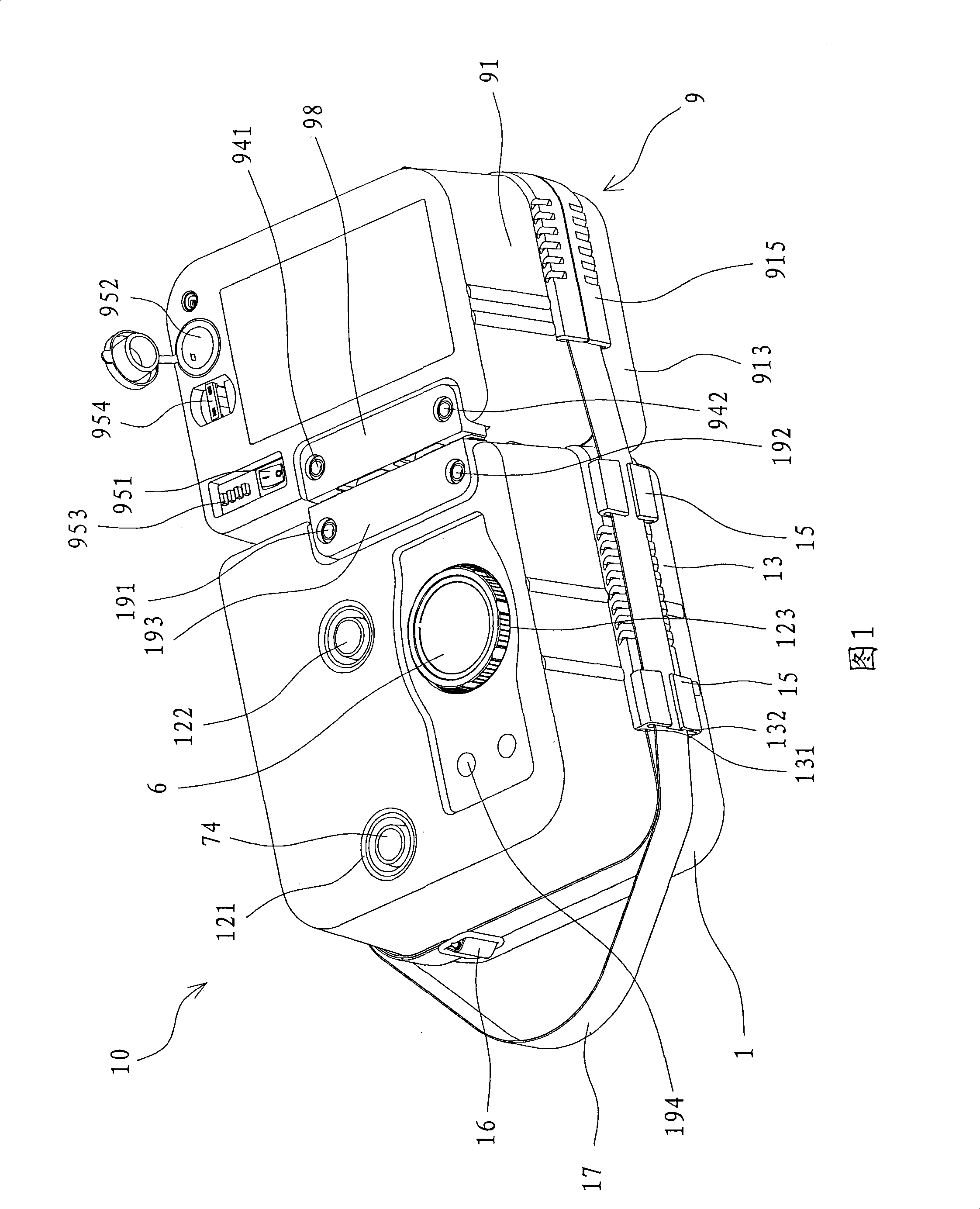
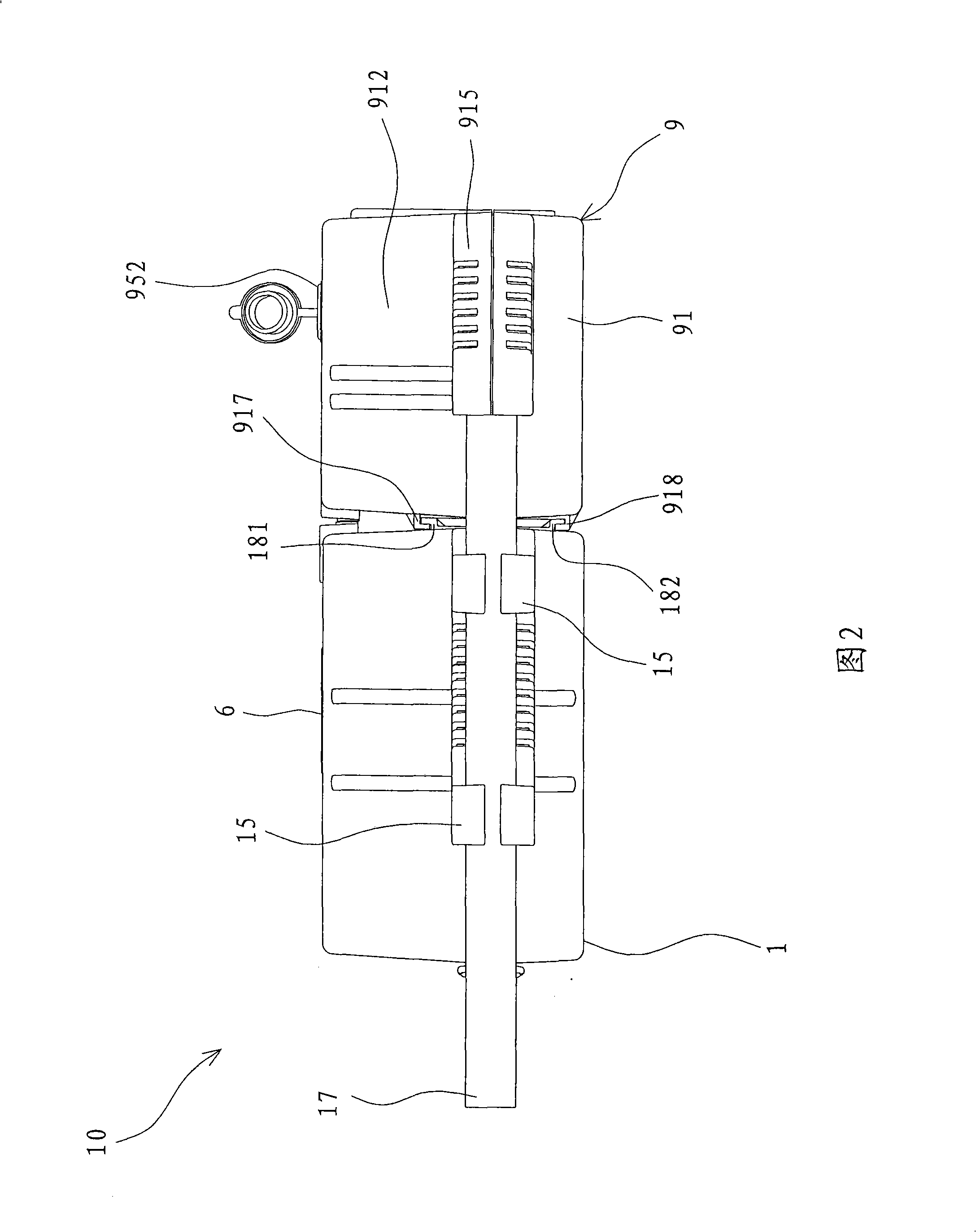
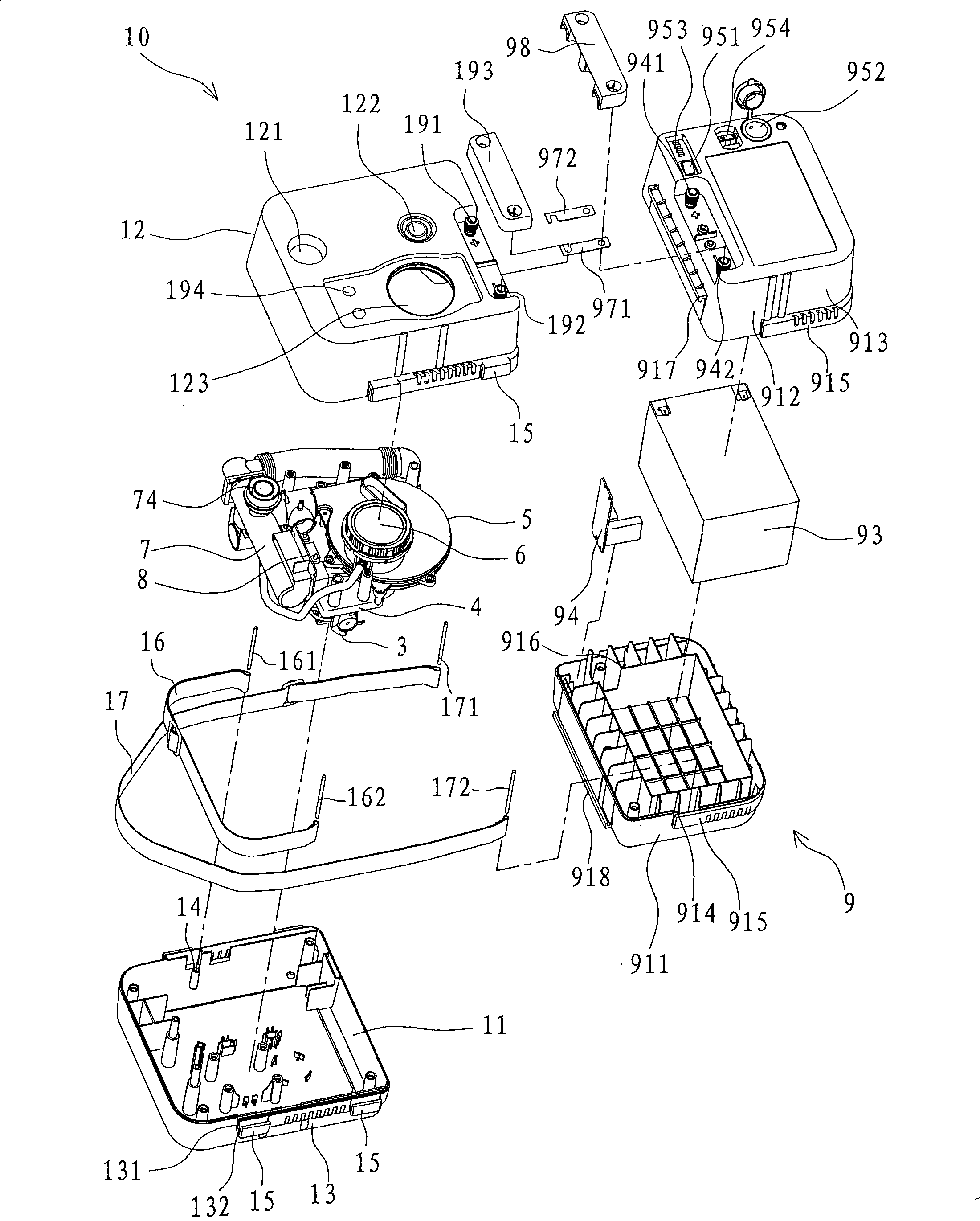
[0057] Refer to Figure 1 to image 3 Shown is an inflatable device 10 composed of a preferred embodiment of the present invention, including a box body 1, a first gas compression device 5, a second gas compression device 3, a gas storage pipe 7, and a control device 8 And a battery device 9 .

[0058] In this embodiment, the box body 1 is composed of a lower cover 11 with an opening upward and an upper cover 12 with an opening downward; two opposite side walls 13 of the box body 1 have a first belt hole 131 and a first Two belt holes 132, the two belt holes 131, 132 are defined by the inside of the L-shaped flap 15 extending outward from the side wall 13, and the second belt hole 132 is located outside the first belt hole 131; wherein, the first The belt hole 131 can pass through the first belt body 16, and the two ends of the first belt body 16 are respectively fixed in the fixing holes 14 provided inside the lower cover 11 by two bolts 161, 162, and the second belt hole 132 ...


PUM


Abstract

The invention discloses an inflation mechanism, which comprises a box body, a first gas compression device, a second gas compression device, a gas storage pipe and a control device; the box body is internally provided with a holding space; the first gas compression device is installed in the box body and provided with a first motor, a gas cabin body and a vent hole which is communicated with the gas cabin body; the second gas compression device is installed in the box body and provided with a second motor, a first compression cylinder and an air outlet which is communicated with the first compression cylinder; the gas storage pipe is installed in the box body and provided with an exhaust port, a first interface connected with the vent hole and a second interface connected with the air outlet; the control device is installed in the box body and comprises a central processing unit which is electrically connected with the first motor and the second motor; and the control device measures the pressure value of the pressurized gas, and controls the first motor and the second motor to operate successively, so as to respectively output the pressurized gas into the gas storage pipe, and the pressurized gas is output through the exhaust port. The structure has short inflation time and high inflation efficiency, and can be used for air escape.

Description

technical field [0001] The invention relates to an inflatable device, in particular to an inflatable device with two functions of inflating and deflating. The inflating device can carry out two-stage inflation of low pressure, high flow rate and high pressure, low flow rate, and has high inflation efficiency. Background technique [0002] Inflatable devices are widely used in inflation operations such as lifeboats, rubber rafts and tires. In order to generate pressurized gas and drive it into the object to be inflated, the general inflator is composed of an air compressor, which has a gas compression cylinder and a piston, and the piston can be driven by a motor. The gas compression cylinder reciprocates to complete the suction, compression and generation of pressurized gas. [0003] Although commonly used air compressors can generate high-pressure gas for inflating, however, the gas flow rate it can generate is small. When it is used in objects that require a large amount ...

Claims


Application Information

Patent Timeline
IPC IPC(8): F04B41/06F04B35/00F04D25/16F04D25/02
Inventor 周文三
Owner 周文三
Why Eureka
Try Eureka